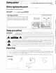
3 Getting started ,. : A Caution Bead this gaps carefullest to ensure safe operation. Before applying the power Units are designed for operation as follows, T i R SALYUT. and Canad *“Other countries .. .. AC 120V ally AC 110-120/ 220-240 V switchable * AC voltage selection AC voltage detector switch Thea AC valiance defector Switch on the rear pang is 58110 the voltage. that prevails in the area ta which the unt is shipped.
True home theater sound This receiver incorporates aide varsity of surround dames to bring you maximum enjoyment from our video software. Sel a surround mode according to your equipment or the software you are going to play and enjoy! Dolby Digital (AC-3} The DOLBY DIGITAL (AC-3) mode lets you enjoy full digital surround from software processed in the Dolby Digital AC-3) format. Dolby Digital (AC-3) provides up to 5.
RDS (Radio Data System) tuner The receiver is equipped with a RDS tuner that provides several convenient twining functions: RDS Auto Memory, to autocratically preset up to 40 RDS stations broadcasting different programs; station name display, 10 show you the name af the current broadcast station; and PTY search ta iet you tune stations by program type.
ROS indicators SURROUND, orgasmic frees crane display, AC3 Suiting mage diplopia and indicators starred 0 ISE drumbeat 7 MEMORY ooy AUTO masticate STEREO radiator ROOM originators Speaker indicators 3 STEED indicator I S.DIRECT indicator L neuron locator LOUDNESS TAPE 2 © POWER key NONSTANDARD -2 6 Tone Control knobs © Numeric keys & STANDBY indicator ©2CH DOWN MIX indicator © SOURCE DIRECT key © DOLBY 3 STEREO key © DOLBY DIGITAL ke About the STANDBY indicator & STANDBY indicator. W) nit modernity.
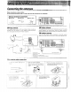
Connecting the . Maker connections as shown below. ASIMOV not connect the power cord to a wall outlet until all connections are completed. Antenna terminal connections © Push lever. £ Insert cord. © Return lever, AM loop antenna The supplied loop antenna is for use indoors.
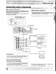
Connecting audio components Make connections as shown below. When connecting the related system components, be sure o also refer to the instruction manuals supplied with the i nonoperational ot possible or an erroneous display components you are connecting, P b ot splay appears, even . though all connections have been mage properly, reset the Do not connect the power cord to a wall outlet until alt microcomputer referring to “In case of difficulty”.
Connecting video components_ Make connections as shown below. When connecting the related system components, be sure to also refer to the instruction manuals supplied with the components you are connecting. Do not connect the parer cord to a wall outset until all connections are completed.
080VR 1En/K) Make connections as shown below. The digital in jacks can accept either Dolby Digital {AC-3} or PCM signals {the input signal type is detected automatically). When connecting the related system components, be sure to also refer to the instruction manuals supplied with the components you are connecting. Do nat connect the power cord to a wall outlet until all connections are completed, Connote components capable of outputting Dolby Digital (AC-3) or standard PCM format digital signals.
PRE OUT connections This receiver has additional printout jacks. These can be used for various purposes, but will need to be connected to an external power amplifier as shown in the example below. Connecting a speaker cord directly to a PRE OUT jack will not produce any sound from the speaker.
Setting up the system 1080V IF « Making connections to another room (ROOM) The following connections allow you 10 connect your main system to a monitor TV and speaker system located 1n stanches area ROOM BJ. The monitor TV oan be connected directly 1o the SECOND ROOM PRE QUT DIVED jack. To connect the speakers, use dither o connections described below. he Te select the input and adjust the volume {etc ) for your other area (ROOM B), set the remote control to the ROOM B aeration made.
e DR Loading the batteries © Remove the cover. @ Insert the batteries. € Close the cover. ik e i «Insert four AAA-size (L RO3) batteries as indicated by the palatal markings. 2. Replace 3il four batteries with new ans when you notice a shortening of the distance from which the remote control wolf operate or if the cermet contra blinks B times when you push a key. The remote control is designed to retain set up codes in memory wile you sangs batiste 3.
This receiver incorporates an on screen display {050} feature to simplify the surround setup procedure by providing sarge easy 1o read graphic information. The section below shows you how to operate the on-screen display. Read this first before going on to the surround setup procedures on the following pages.
S0B0VR fEn /K] 1 Surround setup. To obtain the most possible enjoyment from the receiver's various surround modes, be sure to complete the surround set up as shown below. Speaker placement, Front speakers : Place to the front left and right of the listening position. Front speakers are required for all surround modes. Center speaker Place front and center. This speaker stabilizes the sound image and helps recreate sound motion. Be sure to connect a center speaker when using the Dolby 3 Ste rec mode.
Adjust the volume levels of each speaker. Listen to the test tone and adjust the value level of each speaker so that they all produce the test tong &t the same volume label © Select the test tone type, AUTO : The test tone switches between each speaker in regular intervals SETUP MANUAL : The test tone only comes from the selected speaker displayed in bug) OFF +Stops the test tone. © Adjust the Volume level of each speaker. ¥ Listen to the test tone and select the speaker you want 1o adjust.
playback . Listening to a source component B2 set speakers SPEAKERS B et section e O Start playback from the selected source. E Adjust the volume. S * Surround modes cannot be activated when goth SPEAKERS A and SPEAKERS B are set to ON.
To adjust the balance Use the test tone feature. Adjusting the sound AR Adjusting the tone Frequency welterweight {LOUDNESS} LOUDNESS its you emphasize the sound of frequencies that are difficult 1o hear, The frequency emphasis varies according to e, the volume at which you are listening S To cancel Press again. LOUDNESS Muting the sound MUTE =15 vo e BAIT T N e VLD T Blurs whee: m: To cancel Press again.
SOURCE DIRECT playback 10N 0 pass the source mates! direct to the amplifier, bypassing any audio processing. Usg this Listening with headphones @ Select a playback source, NPT SELECTOR @ Press the SCARCE DIRECT key. ‘SPURGE DIRECT Z\@ > 8 Start playback @ Turn OFF both speaker switches. & sprang 8 == @ Connect headphones. © Adjust the volume. VOLUME CONTROL sy =200/ E==h00 Keys oc contrails used i this parathion.
Boardinghouse, Recording a music source © Select the source you want ta record. LT S Elector * To record a digital source, connected 1o the VIDEO jacks, turn the INPUT SELECTOR 1a sect the appropriate component, then press the STEREO key When making 2 digital recording, operations other than volume adjustment may cause the sound 16 chp d Select a source more than TAPE 1 © Set the cassette deck to record. © Start playback, then start recording. Dubbing tapes (TAPE— TAPE] O Press TAPE 2 MONITOR.
T sweep s, @ Select the source you want to record. INPUT SELECTOR © Set the video deck to record. © Start payback, then start recording. +When recording to & VOR connected 10 the VIDEO jacks, select a source other than VIDEO #When recording to a VR connected 10 the VIDEO jacks, select a source other than VIDEO » Corrector 2 digital source, connected ta the VIDEO 2,3, or 4 jacks, turn the INPUT SELECTOR o select the appropriate component, then press the STEREO key When making a digital recording.
Radio stations can be classified into RDS {Radio Data System) stations and other stations. To listen to or store RDS stations in the preset memory, see the section entities, v Using RDS". Tuning (nonrigid) radio stations PRI Set the input to tuner. PUT SELECTOR Select a station. Frequency dispirit e Heed . Each press switches the band as follows: SAM® or YEM™ indicator Each press switches the tuning method as follows: [ AUTO Bt {auto tuning) 2.
INPUT SELECTOR B Enter the frequency, © Press the DIRECT key. omit Tuning radio stations by frequency (DIRECT tuning) e Set the input to tuner. Frequency daisy T rare ™ Bfl.uum Each press switches the band as follows: chaperoned I I%. V. Press the numeric keys in the following order: * AM 10 kHz/FM 100kHz tuning space Canada, etc.} AM 810 kHz, press AM 1260 kHz, press FM 90 MHz, press FM 102.5 MHz, press AM 810 kHz, press AM 1280 kHz, press M 90 MHz, press FM 102.5 MHz, press 1.0.2.5.
Using RDS (Radio Data System_ RDS is a system that transmits useful information {in the form of digital data} for FM broadcasts along with the broadcast signet. Tuners and receivers designed for RDS reception can extract the information from the broadcast signal for use with various functions, such as automatic display of the station name.
# Before listening to an RDS broadcast, follow the instructions § below to store the RDS stations in the preset memory. stations can be preset, and then received with the * touch of a singe button. This receiver uses the Radio Data System {RDS) to provide convenient tuning functions like PTY search and TP search. Presetting RDS stations (COMMEMORATOR) This function automatically stores up to 40 RDS stations in the preset memory.
The RDS auto memory function assigns preset numbers to RDS stations starting from preset number "1". Therefore, be sure to execute the RDS auto memory function before using the following operations to manually store AM stations and other FM stations, and RDS stations. “Presetting RDS stations {RDS AUTO MEMORY)”. -5 Preparation « select weer Presetting radio stations © Tune to the station you want to store. © Crass the MEMORY key while receiving the station. MEMORY = Proceed 1 step @ within B scorecards.
¥ * This function lets you set the tuner to automatically search m for stations high are currently broadcasting the type of program {genre) you want to listen to, Under certain receiving conditions, it may take more than 1 minute to complete the search, P,epamfim,s Execute the DS auto memory procedure. Set the broadcast band o FM. * Tuna 10 an RDS station Tuning by program type Activate the PTY search mode. 090V Select the program type you desire.
When the receiver is tuned to an RDS station {a station at which the RDS indicator lights up}, this function lets you set the receiver to search for stations broadcasting traffic programs. Preparation + settee broadcast band ©© FM Complete steps B~ of "Presetting RDS stations (RDS AUTO MEMORY}" -8 E Tune to a preset RDS station. Choose an RDS preset station that displays the "RDS" indicator.
1080TH (En/K) This receiver incorporates 4 different sound modes to let you enjoy surround sound with a wide variety of program sources. The Dolby Digital (AC-3) and Dolby Pro Logic surround sound let you enjoy theater-like surround affects when you play Dolby * Digital {AC-3} and Dolby Pro Logic program sources {like Laser discs and DVDs}.
R 108OVR En/K; DSP mode The DSP mode lets you add the atmosphere of an arena, jazz club, or stadium to almost any type of program seurce.® These modes are particularly effective when used with stereo program sources, like CD, television, and FM radio. You might enjoy trying the STADIUM or ARENA mode the next time you watch a concert or sporting event! The WALL parameter lets you adjust the “brightness” of the sonic environment according to your preference.
1CBOVR En/K; DOLBY AC-3 can be used when playing DVD or LD software bearing the EXPRESSWAY) mark and DOLBY DIGITAL {AG-3] format digital broadcasts (etc.. DOLBY PRO LOGIC and DOLBY 3 STEREO can be used when playing video, DVD, or LD software bearing the [Xi[ehsvsmmme] mark. DSP modes can be used with any source. Be sure to complete "Surround set up" before using any of these surround modes. Preparations * Turn ON related components + Com piste "Surround set up'.
R To select a DSP mode @ Press the DSP con, © Select a DSP mode ARENA : Simulates the presence indoor concert arena JAZZ CLUB : Simulates the presence of a jazz club. STADIUM : Simulates the presence of an outdoor stadium CHURCH : Simulates the presence of a church with high ceilings. THEATER : Simulates the presence of a movie theater. To adjust the DSP modes Adjusting the WALL tape. ROOM SINE, and EFFECT LEVEL let you create different types of surround effects.
08D switch When recording programs of watching Davies you may want 1 turn of the OSD display mode. When the OSD display mode 1s ON, each operation of the remote control is displayed on the monitor TV. When OSD display mode is OFF, the receiver will only shows the on-screen display when the SOUND or SETUP keys are pressed. Press to switch, On [ off 05D) SOURCE DIRECT switch Lets you pass the source material direct ta the amplifier, bypassing any audio processing.
1010007 S0y 108AVR ek The remote control supplied with this receiver is lase capable of controlling components from a variety of manufacturers once” you register the appropriate setup codes into the remote control unit. Refer to “Remote operation of other components” for details about the operations available for each component.
Enter the setup code. Merit THEMES EAV OO TWOSOME BEND TAUT FEDERAL RANDOM Clayier E Press POWER, and check to see that the component you want to control turns on. B Tress the ENT key to store the code you have just input. The back light flashes twice. : ROOM B Repeat steps 3 to 6 for all components you want to control. E] Hold down the ENT key until the back light flashes twice.
Operating other comp This operation lets you elopement the registered components. KEN WOOD audio components with system control turn on and off automatically with the receiver via the system contort connections. © Use the VIDEO, AUDIO, or TV keys to select the component you desire. VIBE e v Q0O Cross the SHIFT key and then press the | ! i POWER key (within 3 seconds). swn' € Press the operation keys you desire. o110 flowery 10BINR En /K m Keys or contrails used in this aeration.
‘This operation lets you change the remote control operation mode without changing the input selector. you may find this useful when you want to control one component while using another. {For example, if you want to rewind the tape deck while listening to a CD.} This operation is also useful if you don't know the which made the remote control is set to. Executing this operation allows you to change or reconfirm the operation mode you desire. STV Changing (confirming) the operation mode . .
The macro play function allows you to set the remote to control several components in succession, After completing this setup, you can perform a series of operations automatically. Enter the setup codes for the components you want to control beforehand. B toys o compromise used in this operation i Preparing for automatic operations (MACRO play) Make a plan of the macro play you want to set steps can be sermonized for each macro.
Select where the macro should be stored. Press the VIDEO, AUDIO, or TV key to select the sacra location. (MACRO. 2, and 3 respectively) Audio 509 \\ Press the keys to be operated in order. @ Press TV » SHIFT » POWER to i PLE: EXAMPLE turn on the TV, SHIFT v ( oversea Press FUNCTION SHIFT » "4 (TV/ 1o set the TV ta the misappropriate video input. TV/SAT. D \ FUNCTION N SHIFT (¢ € Crass DIVED twice to select the LD player registered at VIDEO 2.
Executing an automatic operation. Press the MACRO key. E Execute the macro play. [ Press the VIDEO, AUDIO, execute the correspond ing macro play. ‘f" vogue (oMY wY your latecomer ; BASRA En .
you make connections to another room, you can use the remote control to select source components and to adjust the volume {etc.} output to the other room, -3 «KEN WOOD system control operation are ably possible wain the £Mote Control s 561 1o the Rom A perpetration mode.
s 1aaue] spunky S s Setup code correlation Deleting a setup code [ @ Hold down the ENT kay until the back light flashes twice. | © Select the component to be deleted. Press the VIDEO, AUDIT, or TV key repeatedly to select the desired component. | & Enter the 3 digit code 391", i @ Hold down the ENT key until the back light flashes twice. Checking a setup code © Hold down the ENT key until the back light flashes twice. © Detect the component with setup code you want to cheek.
e Gatling G300 ) Future Set allows you to update the remote control so it can operate new components which do not appear in the setup code list at the end of the manual. “This function allows you to register new setup codes for any or all of the following command positions: VIDEO, VIDEO, VIDEO, VIDEOS, TV1, TVZ, CABLE, €D, TAPPED. Future Set codes 8re stored in memory. Each time a Future Set upgrade is performed, any previous information in the Future Set memory location s erased.
TOBOGGAN (Er k) E Hold your remote to the speaker portion of your telephone. e « For each setup code the aerator can supply » setup code number. Should you ever need to change your put configuration. this number Gan b used. Please record for your future reference. If for some reason this information is 1051, see “Checking 8 stun code’ in the "Setup code correlation” section for further information.
Non-IR codes D player 8300 Satellite 2900 DVD 6900 Cassette dock 7900 W 1900 Dss 3900 LD player 5900 ver 4300 ) 8900 Phonon 0900 VCR Set up codes Maker 8et up codes Maker Set up codes Maker Set up codes Action 4317 De Graft 4042 Harmonization 4038 behavioral 4000 Decca 4000, 4081 Far wood 2072 Ao 4278 Dl 2041 M 4077 Awa 4000, 4307, 4408 | document 4000, 4081, 4104 | headquarter 4048 Aral 4041, 4315 Dynamite 4000 HIQ 4047 Akiva 4072 Hellcat 4077 Dinar 4072, 4240 Alba 2278, 4295 Electromotive 2037 Hitachi 400
PO VCR Set up codes (continued) Maker Set up codes Maker Set up codes Maker $et up codes Extreme 4000, 4035, 4037 | Pioneer 4067, 4081 Siva 4037 4039, 4046, 4047, interoffice 4240 Singer 4045, 4072 igloo' 4104, 4290 Ip e 4000 Sinuosity 2081 Messiahs o7 erect jg;g become gill 4033, 4034 Met 4162, 4454 Pye 4081 035 MGA 4043 ST 4047 Quarter 4046 042 MGN Technology 4240 e oo Mainline 4042 Quartz 4045 not o H0%5 a557 08T Quasar 4035, 4077, 4162, Suntrap 4000 rubbish g BOBTAIL 4254 Sassanian 4000, 4035, 4043, Que
TV Set up codes Maker Set up codes Maker Set up codes Maker Set up codes Admiral 1093 GE 1021, 1027, 1047 [NEC 1019, 1030, 1056 Adventure 1046 1081, 1055, 1135, UNESCO 1179 ko ) 1176, 1282, 1451 Nikki 1080, 1082, 1178 Aka 1030 Scenery 1185 Nos hi 1018 e oo Gibraltar (SCHEMATICS] S e e Ambassador 1177 Gold star :g;g: w0l o 7180 Amsterdam 1177 Goodman 1175 Optimums, 1154, 11686, 1250 Ans 1180 Gran din 1283 Catatonic 1083, 1165 “Ana Naval 1055, 1250 G e T Orin 177, 1236 AOC 10787030, 1137] Flirt e Panasonic 10
G o an 1080 /i TV Set up codes (continued) Maker Set up codes Maker Set up codes Maker Set up codes Sinuosity 1177 Gatun 1055 Triumph 1177 Sony 1000 Technicians 1051, 1250 Universal 1027 Undersign 1178, 1178, 1180, Techno Ace 1178 Vector Research 1030 1186 Tech wood 1061, 1056 Victor 1053, 1250 Spectroscopic 137 Tektite 1018, 1018, 1039, Dravidian 1054 585 1019, 1180 1054, 1056, 1060, Via tech 1019, 1178 Sta rite 1180 1092, 11501178 TS 10461312 1180, 1186, 1312 Sucre 1086 Tor T Wards 1016, 1019, 1021, Sucre
Cable Set up codes Maker Set up codes Maker Set up codes Maker Set up codes ABC 0001, 0003, 0007, Hitachi 0011 Scientific Atlanta 0008, 0017, 0477 0008, 0011, 0013, Hypertext 0007 Signal 0015, 0040 0014, 0077 Ascot 0153 Signature 0011 Antineutron 2022 Jerrold 0003, 0011, 0012, {SL Man.
é DAT deck Set up codes Maker Set up codes Maker Set up codes Maker Set up codes Carver 7158 Mantra 7168 Sony 7083 Deon 7031 Philips 7158 Technicians 7158 Grounding 7158 Cassette deck Set up codes Maker Set up codes Maker Set up codes Maker Set up codes Away 7028, 7197 JVC 7244, 7273, 7274 Rev ox 7029 Ar cam TOTE Ken wood 7000, 7071, 7183 Sanguine 7009, 7028 Carver 7029 Magnate 7029 Sony 7170, 7243, 7291 Deon 7076 Mantra 7008, 7028 Te ac 7308, 7303 Fisher 7074 Yonks 7136 Technicians 7228 Asgard 7308, 7308 O
ARG ,;5, In m af dtffiwlty M&Lfl Walesa R 308018 g The back light flashes five times during normal operation. * The batteries are anneal exhaustion * Replace with new batteries to preserve the current registered setup information. 21§ Subway volume cannot be adjusted. * Sunroof s OFF Turk the sub woofer ON = Certain inputs cannot be selected using the remote control.
AUDIO section Rated power output during STEED operation 150 watts per channel minimum RMS, both channels driven, at 6 (1 from kHz with no more than 0.03 % total harmonic Rated power output during SURROUND operation FRONT {KHz, 0.7% T.H.D. CENTER {kHz, 0.7% TH.D. at 6 0 SURROUND {kHz, 0.7% TH.D. at 6 Q) Total harmonic distortion . Frequency response D .. kHz, 75W, kHz, +0.5 dB, -3 4B Signal to noise ratio PONG (MM}, PHONON (MM\ 25mV /47 kQ 200 om put level { impedance TAPE BEC 200 mV 7 470 Q2 PRE OUT (FRONT,
Refer to the following for the type of remote control operations available for each component. The setup code for each component must be entered beforehand © Use the AUDIO, VIDEO, or TV kens to select the component you want to control. 6 Cross the keys corresponding 1o the operations you desire. Refer to the following sections for details. 3 -3 *When pressing keys in succession, press each key firmly and be sure 10 wait at least 1 second before pressing the next key.
Remote operation of other components PO Mode! _ Senate Number 1050V /) & | DSS receiver operations HOODED OO sne o DO HEBE = @@9 OOE OO (CH Guide) {Channel +} »/8 (Select) Numeric keys FUNCTION SHIFT commands {Channel -} "y MENU {(Menu} n (b THEME (Theme) () FAV. {Favorite} () {Input selector} INFO (information} ALT AUDIO (Alternate audio} +100 {+ 100} Cable tuner operations ague ROOD (OSD menu) {Select) Numeric keys FUNCTION SHIFT commands LINE 3] MENU (Menu) w (b * THEME (Therm) . (4o FAV.