Cellular 500W Remote Module Installation Guide xx DRAFT xx ITRON INSTALLATION GUIDE October 11, 2021 815-0618-00 REV 000 Itron, Inc.
Cellular 500W Remote Module Installation Guide October 11, 2021 815-0618-00 REV 000 Copyright © 2021 Itron, Inc. All rights reserved. Confidentiality Notice Confidential Information of Itron®, Inc., provided under nondisclosure obligations. The information contained herein is proprietary and confidential and is being provided subject to the condition that (i) it be held in confidence except to the extent required otherwise by law and (ii) it will be used only for the purposes described herein.
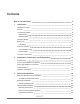
Contents Cellular 500W Remote Module Installation Guide 1 Contents 3 New in This Document 5 1 Introduction 6 Related Documents 7 Security 8 Transmission Modes 8 Mobile Mode 8 Network Mode 8 Operating Modes 9 10 Battery Life Low Battery 10 10 Events and Alarms 2 3 Extended Alarm Flag 10 Network Mode 11 Firmware Functionality 11 Initialization, Connection, and Programming 13 Programming 13 Encoder-type Register Connections 14 Pulser-type Register Connections 16 Cable Ex
Cellular 500W Remote Module Installation Guide Table of Contents Remote Mount Installation 31 33 Remote Disconnect Valve Installation Wire Connections 4 34 Leak Sensor Installation 34 Itron Cable Armor Installation 34 To install the cable armor 36 Completing Gel-cap Connections Using the Itron Splice Tube Kit 38 Required Materials 38 To complete gel-cap connections 38 5 Troubleshooting 41 6 Important Safety and Compliance Information 42 USA, FCC Part 15 Spectrum Compliance 42 USA,
New in This Document Revision 000 Date September 2021 Description First publication. DRAFT October 11, 2021 815-0618-00 REV 000 Itron, Inc.
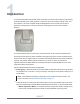
1 Introduction The Cellular 500W Remote Module (ECW-1700-002) is a cellular radio frequency transmitting modules that attaches to water registers or meters to collect consumption usage, event, and alarm data. It is an IPV6-compliant endpoint designated to communicate over the Itron’s OpenWay multi-purpose IoT solution: Network or the legacy ChoiceConnect™ Mobile platform. The Cellular 500Ws ship from the factory in Factory Mode, which prevents unwanted radio transmissions during transit.
Cellular 500W Remote Module Installation Guide 1 Introduction – Mobile and Handheld Mode. The module transmits a medium-powered RF message every 15 seconds. In Mobile and Handheld Mode, the expected battery life is 20 years. – (Optional) Hard-to-Read Mode. The module transmits a high-powered RF message every 30 seconds. In Hard-to-Read Mode, the expected battery life decreases to 15 years in this mode.
Cellular 500W Remote Module Installation Guide 1 Introduction ■ OpenWay Riva Water Products Ordering Guide ■ Water Modules Ordering Guide Security Users have the option of enabling enhanced security in Cellular 500Ws. Itron Security Manager (ISM) is a feature of the OpenWay Network that ensures that certain Cellular 500W commands are controlled through secure radio communications between the handheld computer or Mobile Collector and the Cellular 500W .
Cellular 500W Remote Module Installation Guide 1 Introduction Note: Interval data configuration is dependent on the module's firmware version. See Firmware Functionality on page 11 for more information. The Cellular 500W also sends a local access beacon message every 60 seconds that allows users to gather contingency readings locally when needed. Caution: If you perform a switch to Network Mode or switch to Mobile Mode operation, it results in a loss of interval data.
Cellular 500W Remote Module Installation Guide ■ 1 Introduction Quiet Mode – Meter manufacturers can configure the Cellular 500W for Quiet Mode after programming and direct mounting the Cellular 500W in a factory. – The Cellular 500W is awakened from Quiet Mode and enters Run Mode in one of the following ways: • Counting two pulses. The pulses are counted internal to the Cellular 500W while it is in Quiet Mode. • Receiving a two-way command, such as a Read using FDM.
Cellular 500W Remote Module Installation Guide ■ 1 Introduction The low battery warning allows the utility to easily identify which Cellular 500Ws are nearing end-of-life in a mixed population and gives the utility the opportunity to schedule replacement. The remote modules include a battery life estimator. The estimator is based on the number of data packets sent at the various power levels and the age (self-discharge) of the Cellular 500W .
Cellular 500W Remote Module Installation Guide Firmware part number FMW-xxxx-xxx- [4.4.2] Global software release version (GSR) 5.4 1 Introduction FDM Check Endpoint firmware version 4.4.0 Over-the-air firmware part number DFW-xxx-xxx Firmware functionality ■ Initial firmware release ■ Network Mode ■ Mobile Mode ■ 60 minute interval data ■ Firmware download DRAFT October 11, 2021 815-0618-00 REV 000 Itron, Inc.
2 Initialization, Connection, and Programming This chapter provides the instructions to initialize and connect the Cellular 500W to the meter or register. Cellular 500Ws must be connected to the register or meter before they can be installed. Requirements are based on the network system mode. The Cellular 500W 's auto-sensing technology eliminates the need to initialize the module at the time of installation. The module automatically detects the connected register type.
Cellular 500W Remote Module Installation Guide 2 Initialization, Connection, and Programming Caution: The FC300SR or Itron Mobile Radio are the only devices that support programming for the remote module endpoint. The remote module and programmer should be a minimum of 12 inches apart while programming. Do not place the programmer antenna directly on the remote module.
Cellular 500W Remote Module Installation Guide 2 Initialization, Connection, and Programming Cellular 500W wire color Brown (data) Register manufacturer Gray (power/clock) Yellow (ground) Register screw color designator ■ Elster AMCO evoQ4 Mag Red White Black ■ Itron (Actaris) Cyble Coder Green Red Black ■ Kamstrup flowIQ2100 Green Red Black ■ MasterMeter Green Red Black ■ Acculinx ■ Octave ■ McCrometer Green/data port Red/clock port Black/GND port ■ Metron Farnier OER G
Cellular 500W Remote Module Installation Guide 2 Initialization, Connection, and Programming Pulser-type Register Connections Connect the Cellular 500W cable to the register according to the following table.
Cellular 500W Remote Module Installation Guide 2 Initialization, Connection, and Programming ■ FC300SR handheld computer ■ Itron Mobile Radio connected to a user-supplied computer or Bluetooth device Caution: Verifying the Cellular 500W operation requires an FC300SR handheld computer or Itron Mobile Radio running FDM v4.0 or higher. Legacy Itron handheld programming devices cannot read the Cellular 500W .
3 Setup and Installation This section describes the installation process for the Cellular 500W Pit Module and its necessary and optional accessories. Read this chapter in the order it is provided, as certain procedures must be completed ahead of the Cellular 500W Pit Module installation. Module Cable Strain Relief Installation After you complete the Cellular 500W to register connections, install a cable tie to the meter cable just below the exposed colored lead wires on the cable insulation.
Cellular 500W Remote Module Installation Guide 3 Setup and Installation 5. If your cable tie gun is equipped with a dial to set the tightening pressure, set the pressure to ensure that the cable tie is secure on the lead wire. After installation, the cable tie must not move on the register or secondary lead wire. 6. If your cable tie gun does not have a clipping feature, remove the cable tie from the cable tie gun. Using a side cutter pliers, clip the excess cable tie. 7.
Cellular 500W Remote Module Installation Guide 3 Setup and Installation Backplate Installation After the connections are made to the register and optional telemetry device, attach the Cellular 500W's backplate. Attaching the Backplate 1. Route the register cable and telemetry device cable through the dual-port backplate. Ensure that the cable strain reliefs are inside the module housing and backplate assembly. 2.
Cellular 500W Remote Module Installation Guide 3 Setup and Installation 3. Align the remote module backplate with the mounting screw holes. Verify that the Itron logo is not upside down. 4. Insert a backplate mounting screw in one corner and tighten the screw two or three turns. Insert the remaining three screws and tighten each a few turns. DRAFT October 11, 2021 815-0618-00 REV 000 Itron, Inc.
Cellular 500W Remote Module Installation Guide 3 Setup and Installation 5. Completely tighten all screws evenly in an alternating fashion. Mount the remote module after the backplate is attached. See Cellular 500W Installation on page 22. Cellular 500W Installation Warning! Internal circuit card components may be sensitive to electrostatic discharge. Be careful not to touch any part of the meter body, register housing, or remote module prior to discharging any static buildup on your person.
Cellular 500W Remote Module Installation Guide 3 Setup and Installation mount kit. Important! While Itron modules are designed to withstand a drop, dropping the module can damage sensitive electronic components and void the product warranty.
Cellular 500W Remote Module Installation Guide 3 Setup and Installation To direct mount on the ABB Scancoder, InVision, or Digital Direct Mount Note: Verify that you have an Elster/AMCO meter with a register designed for direct mount Cellular 500W . Always install the Cellular 500W right side up with the arrow on the housing pointed upward. The register may or may not be mounted on the meter when performing the following steps. 1.
Cellular 500W Remote Module Installation Guide 3 Setup and Installation 6. Connect the Cellular 500W wires to the register screw terminals following the Cellular 500W to the Elster/AMCO meter register wire connections. After the wires are connected, carefully tuck the connectors into the Cellular 500W housing. Tighten all screws securely. Caution: Install the wires around the screws in a clockwise direction (as shown) or the wires may come out from under the screw heads as you tighten them.
Cellular 500W Remote Module Installation Guide 3 Setup and Installation 1. The Cellular 500W has three wires that connect to the register: 2. Connect the Cellular 500W wires to the register using gel-cap connectors following the Cellular 500W to the Badger ADE register wire connections (see Encoder-type Register Connections on page 14). 3. After the wires are connected, carefully tuck the connectors into the Cellular 500W housing. DRAFT October 11, 2021 815-0618-00 REV 000 Itron, Inc.
Cellular 500W Remote Module Installation Guide 3 Setup and Installation 4. To wire the Cellular 500W to the RTR two wire register, connect the Cellular 500W wires to the two wire register using gel-cap connectors. After the wires are connected, carefully tuck the connectors into the Cellular 500W housing. 5. Place the Cellular 500W on the register, ensuring that the edge of the Cellular 500W housing is seated properly around the perimeter of the register as shown. Note: A gasket is not required. 6.
Cellular 500W Remote Module Installation Guide 3 Setup and Installation Warning! Use Itron mounting screws (SCR-0010-005). Using the wrong mounting screws could crack the plastic module housing. 7. If you have not already done so, connect the register to the water meter and fully tighten the mounting screw (1) as directed by Badger Meter instructions.
Cellular 500W Remote Module Installation Guide 3 Setup and Installation 8. If the standard Torx screw is used (1), a wire seal is not necessary. If the optional slotted and drilled RTR screw is used, install a wire seal through the drilled screw from (1) to (2), or as specified by utility policy. Pipe Mount Installation The Cellular 500W can mount on a pipe vertically, diagonally, or horizontally using a pipe mount kit and remote mount kit (see Mounting Accessories on page 23).
Cellular 500W Remote Module Installation Guide 3 Setup and Installation 5. Push the end of the band through the band clamp screw assembly. Turn the band clamp's screw assembly to fit into the pipe bracket opening. Tighten the clamp screw until the band clamp is secure on the pipe. Adapter Plate Mounting Positions The installation procedure in the previous section shows how to mount the adapter plate on a vertical pipe. The following pictures show the adapter plate on 45-degree angle and horizontal pipes.
Cellular 500W Remote Module Installation Guide 3 Setup and Installation To mount on the adapter plate 1. Locate the two 1 inch Cellular 500W mounting screws in the pipe mount kit. 2. Slide the Cellular 500W back cover onto the adapter, pushing up to secure the lug adapter in the lug slot. 3. Install the two 1 inch Cellular 500W mounting screws. 4. Tighten the screws to 9 to 12 inch-pounds of torque. Remote Mount Installation 1.
Cellular 500W Remote Module Installation Guide 3 Setup and Installation 2. Using a back plate, create a template by drilling through a back plate lug slot to mark the position of the screw. Use the drilled back plate as your mounting template. The arrow on the Cellular 500W must point up when installation is complete. To install on a flat surface 1. Select an installation location. 2. Using a back plate template, drill three pilot holes into the wall or other surface.
Cellular 500W Remote Module Installation Guide 3 Setup and Installation 6. Insert a tamper seal over each mounting screw and drive into place with a nut driver or a similar tool. Note: A tamper seal is fully seated when the top of the tamper seal is approximately 1/16 inches below the top of the screw recess. 7. Secure any excess cable using the provided cable ties.
Cellular 500W Remote Module Installation Guide 3 Setup and Installation The remote module automatically detects the presence of connected water disconnect devices within 22.5 minutes and begins reading disconnect valve data. To immediately detect the water disconnect valve and begin reading data, perform a Check with a handheld computer running FDM software. The Remote Disconnect Valve connects to the Cellular 500W orange, blue, and purple/white wires.
Cellular 500W Remote Module Installation Guide 3 Setup and Installation Warning! Use caution when you are installing the cable armor. ■ Itron cable armor is stainless steel and may have sharp edges. ■ If you remove the inline connector from the remote module to install the cable armor, you must use an Itron handheld to reprogram the pit module using FDM Endpoint Tools.
Cellular 500W Remote Module Installation Guide 3 Setup and Installation Important! You must twist—not wrap—the cable armor onto the Cellular 500W cable. Wrapping the cable armor can cause the stainless steel jacket to warp. You must begin twisting the cable armorover the portion of the cable protected by the electrical tape. If you do twist the cable armor onto the Cellular 500W cable on the unprotected portion of the Cellular 500W cable, you could damage the module's cable.
Cellular 500W Remote Module Installation Guide 3 Setup and Installation 3. Wrap the entire piece of electrical tape around the Cellular 500W cable near the Cellular 500W . 4. Beginning over the installed electrical tape, twist the Itron cable armor onto the Cellular 500W cable using a right-handed twist. Important! You must twist—not wrap—the cable armor onto the Cellular 500W cable. Wrapping the cable armor can cause the stainless steel jacket to warp.
4 Completing Gel-cap Connections Using the Itron Splice Tube Kit Important! All unused wires on modules must be terminated. Wire terminations must be properly sealed with a non-conductive gel material to prevent water intrusion and possible environmental or electrical issues. Required Materials ■ E-9R 3M® gel connector crimping tool (or other 3M approved crimping tool) ■ Itron splice kit (part number OEM-0034-002) To complete gel-cap connections 1. Push two wires as far as possible into the connector.
Cellular 500W Remote Module Installation Guide 4 Completing Gel-cap Connections Using the Itron Splice Tube Kit 3. Crimp the connector by squeezing the handles until the connector cap is fully seated. Continue to apply pressure for three seconds. 4. A connector is crimped properly when the top of the movable yellow center (1) is flush with the top of the connector body (2). Warning! Crimping the connector forces some sealant out of connector.
Cellular 500W Remote Module Installation Guide 4 Completing Gel-cap Connections Using the Itron Splice Tube Kit 6. Insert the connectors and wires into the splice tube until the connectors and wires are completely immersed in the non-conductive gel material. 7. Separate the cable wires to the sides and close the splice tube cover. 8. Remove any leftover materials from the customer premises. DRAFT October 11, 2021 815-0618-00 REV 000 Itron, Inc.
5 Troubleshooting This information will help you troubleshoot issues related to the Cellular 500W. The following table describes possible issues and provides suggested actions to resolve the issue. Issue Action Cannot program the Cellular 500W. Check the programming device and software version. Program Cellular 500W using an approved handheld computer running Field Deployment Manager (FDM) 4.4 or higher. Cannot read the Cellular 500W. A Cellular 500W that is not programmed does not transmit a SCM+.
6 Important Safety and Compliance Information This section provides important information for your safety and product compliance. USA, FCC Part 15 Spectrum Compliance This device complies with part 15 of the FCC Rules. Operation is subject to the following two conditions: 1. This device may not cause harmful interference, and 2. This device must accept any interference received, including interference that may cause undesired operation.
Cellular 500W Remote Module Installation Guide 6 Important Safety and Compliance Information Modifications and Repairs Warning! This unit cannot be modified and is not repairable. Attempts to modify or repair this module voids the warranty, per FCC and ISED rules. Canada, ISED Spectrum Compliance Compliance Statement Canada Déclaration de Conformité This device complies with Innovation, Science and Economic Development Canada (ISED) licenseexempt RSS standard(s).
Cellular 500W Remote Module Installation Guide 6 Important Safety and Compliance Information ■ The battery used in this device may present a risk of fire or chemical burn if mistreated. ■ Keep the lithium battery away from children. Disconnecting Power Warning! Qualified technicians: during service, disconnect power to prevent ignition of flammable or combustible atmospheres. Electromagnetic Compatibility Warning! Use only approved accessories with this equipment.