7-6 the Multiplexer To GDP To connect a Multiplexer to a GDP, refer to Figure 17.4 and use the following instructions: 1. On the Multiplexer, jumper P12-pin 1 (+12V) to P6-pin 1 (C1) to provide power to that output. 2. Connect P6-pin2 (ST-1) of the Multiplexer to P2-pin 1 (1) of the GDP. The GDP will now receive and display data from Zone 1. For additional GDPs, connect the ST-(#) outputs of the Multiplexer to the (#) inputs of the GDPs.
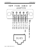
Installation Manual To PC To connect a Multiplexer to a PC, refer to Figure 17.5 -17.6 and use the following instructions: 1. Using CAT5 and a DB9 connector, connect the Multiplexer to a serial port of the PC (serial port #1 recommended). NOTE: Depending on the distance between the Multiplexer and the PC, you may want to use RJ45 wall plates for simplicity. Figure 17.
17-8 the Multiplexer Figure 17.
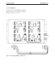
Installation Manual To other Multiplexers To connect two more or Multiplexers, parallel all RS485 connections, one to the next in cascading method. (see Figures 17.7 and 17.8). Figure 17.
17-10 the Multiplexer Figure 17.
Installation Manual the Multiplexer 17-11 Multiplexer board settings Use the board settings below (Table 17.1 and Figure 17.9) for Dip Switch S2 on the Multiplexer. NOTE: Only board 1 (Address 0000) should be plugged into the PC. Table 17.1 Multiplexer Board Settings Board Number Dip Switch Setting 1234 1 0000 2 0001 3 0010 4 0011 5 0100 6 0101 7 0110 8 0111 9 1000 10 1001 11 1010 12 1011 13 1100 14 1101 15 1110 16 1111 Figure 17.
Installation Manual Chapter 18: Power Supply
Installation Manual Power Supply Power Supply Specifications Positioning the Power Supply Mounting the Power Supply Connecting the Power Supply Some installations of the Accutech System peripherals require more power than the Controller can provide. In these cases, a Power Supply (Figure 18-1) is added to the system to meet the additional power requirements.
18-2 Power Supply Figure 18.
Installation Manual Chapter 19: The Accutech Software
Installation Manual The Accutech Software Minimum System Requirements Recommended System Components Installing the Accutech Software Uninstalling the Accutech Software Example System Configuration The Accutech Software (v4.10 or greater) displays incoming event information via the Multiplexer from monitored zones. The PC screen will display events in real-time using the facility’s floor plan as the background.
19-2 the Accutech Software Uninstalling the Accutech Software 1. From the Start menu, Programs, Accutech, select “Remove Accutech Patient Security System”. A confirmation message box appears. 2. Click “Yes”. 3. Click “Close” to exit the uninstaller program. 4. From the Start menu, Programs, Accessories, select “Windows Explorer”. 5. Select the ICS folder (C:\ics) and delete it. 6. Reboot the PC.
Installation Manual Figure 19.
Installation Manual Chapter 20: Tag Test Station
Installation Manual Tag Test Station TTS Specifications Positioning and Mounting a TTS Connecting a TTS The Tag Test Station (TTS) is used for Tag assignments. In a similar fashion to a Tx wand antenna, the TTS emits a small Tx Activation Field that activates Tags. Once activated a Tag sends a signal to the Receiver. The Receiver sends this information to the Multiplexer, which sends it to the computer with the Accutech Software.
20-2 Tag Test Station Figure 20.
Installation Manual Figure 20.
Installation Manual Chapter 21: Band Removal Lockdown
Installation Manual Band Removal Lockdown 21-1 Band Removal Lockdown Wiring Band Removal Lockdown Band Removal Lockdown engages all facility Magnetic Locks when a Band Removal alarm occurs. To wire the Controller for Band Removal Lockdown, refer to Figure 21.1 and use the following instructions: The Multiplexer controls a 12V DC signal that can be sent to the Relay board. The Relay controls a 12V DC signal from each Controller to the Lock(s) at each zone.
21-2 Band Removal Lockdown 6. For each Controller (Lock) you must pick a set of contacts to work with on the Relay Board. The example in Figure 21.1 shows Relay K1 being used: a. Connect P8-3 (+12V) on the Controller to J1 at (K1-Com) on the 8-zone Relay Board. b. Connect P6-1 (Per. Lock) on the Controller to J1 at (K1-NO) on the 8-zone Relay Board. 7. Do the same for contact K2 through K8. 8. If more than 8 zones are being locked, then additional Relay boards will need to be connected. a.
Installation Manual Figure 21.
Installation Manual Chapter 22: User-Defined Settings
Installation Manual User-Defined Settings 22-1 User-Defined Settings Door Ajar Door Ajar Reset Loiter Loiter Reset System Supervise Power Loss Supervise NOTE: The following settings are up to the facility’s discretion. All times are approximate. Door Ajar Reset JP16 determines if the Door Ajar automatically resets once the door is fully closed. Table 22.
22-2 User-Defined Settings Loiter Reset JP10 determines if the Loiter alarm automatically resets once the Tag leaves the zone. Table 22.4 JP10 Position Alarm Automatically Resets? In Yes Out No System Supervise JP5 determines how often the System Supervisor checks the Accutech System. For more information about the System Supervisor, see page 3-6. Table 22.
Installation Manual Appendix A: Discontinued Components
Installation Manual Appendix A: Discontinued Components From time to time, system components may become discontinued due to revisions, improvements, or unavailability from the manufacturer. Appendix A: Discontinued Components A-1 Weight Internal and External Receivers weigh approximately 5.0 oz. and 1 lb. 5.0 oz. U.S. respectively, which should be considered when choosing mounting hardware.
A-2 Appendix A: Discontinued Components Installation Manual Internal vs. External Receivers Receiver Positioning/Stagger Tuning When the Controller is positioned near the monitored zone, the Receiver is mounted internally in the Controller housing. Position the Receiver within approximately 6 feet of the center of the monitored zone or door opening. It is permissible to mount it beyond 6 feet, but do not exceed 15 feet from the center of the zone or door opening.
Installation Manual Figure A.
A-4 Appendix A: Discontinued Components Adjusting the Receiver The Receiver is factory set for optimum performance, and as such, it should not be necessary for you to make any adjustments to it. However, there are some exceptions: When protecting a wide hallway, it may be desirable to increase the Receiver sensitivity to assure optimum detection.
Installation Manual Composite Cable (Part #200355) Lock Cable Technical Specifications NOTE: For easier installation, Accutech Composite Cable (Part # 200355) was replaced with Composite Cable (Part # 200371) on June 1st, 2004 and is no longer in production. For information on the new composite cable (Part # 200371), see page 2-2.
A-6 Appendix A: Discontinued Components Installation Manual Technical Specifications The technical specification for Composite Cable (Part # 200355) 2 Pair of AWG x 7/.0152 T.C., 0.012 Teflon Color Code: black/red; green/white 0.001 polyester tape binder over each pair, 18 AWG x 7/.0152 T.C. drain, 0.0015 aluminum/polyester shield, foil and drain. 2-Conductor 18 AWG x 7/.0152 T.C., 0.008 Kynar, Color Code: brown, blue. 10 Conductor 24 AWG x 7/32 T.C., 0.
Installation Manual Tag styles (gray and/or yellow colored) ES 2200 System Tags IS 3200 System Tags BR 4200 System Tags NOTE: Gray and/or yellow Tag case styles are no longer in production and are replaced with bar-coded Tag case styles. For more information, see Chapter 6. ES 2200 System Tags ES 2200 System Tags (Figure A.8) are small wristwatch-sized devices worn by a resident or attached to an asset.
A-8 Appendix A: Discontinued Components Installation Manual Activating/Deactivating Tags NOTE: The “Tag Signal Strength” LEDs of the TAD (see Figure A.10) indicate the current state of a Tag. Illuminated indicates the Tag is on; dormant indicates the Tag is off or is not functioning. 1. With no Tag in the TAD, slide the Power switch to the On position The TAD Power LED illuminates. If not, replace the TAD 9-volt battery and turn on the TAD.
Installation Manual Appendix B: Jumpers, LEDs, Pots, Switches & Fuses