User Manual
Copyright Information Hytera is the trademark or registered trademark of Hytera Communications Corporation Limited (the Company) in PRC and/or other countries or areas. The Company retains the ownership of its trademarks and product names. All other trademarks and/or product names that may be used in this manual are properties of their respective owners. The product described in this manual may include the Company’s computer programs stored in memory or other media.
FCC Statement This is A 90.219 CLASS A DEVICE. This equipment has been tested and found to comply with the limits for a Class B digital device, pursuant to part 15 of FCC Rules. These limits are designed to provide reasonable protection against harmful interference in a residential installation. This equipment generates and can radiate radio frequency energy. If not installed and used in accordance with the instructions, it may cause harmful interference to radio communications.
Compliance with RF Exposure Standards Hytera's radio complies with the following RF energy exposure standards and guidelines: United States Federal Communications Commission, Code of Federal Regulations; 47 CFR § 1.1307, 1.1310 and 2.1091 American National Standards Institute (ANSI) / Institute of Electrical and Electronic Engineers (IEEE) C95. 1:2005; Canada RSS102 Issue 5 March 2015 Institute of Electrical and Electronic Engineers (IEEE) C95.
User Manual Contents Contents Documentation Information ..................................................................................................................... 1 1. Introduction ........................................................................................................................................... 3 1.1 Product Description ........................................................................................................................... 3 1.2 Highlights ...........
Contents User Manual 5. Power On and Power Off .................................................................................................................... 36 5.1 Powering On .................................................................................................................................... 36 5.2 Powering Off .................................................................................................................................... 36 6. Debugging .........................
User Manual Documentation Information Documentation Information This section describes the audiences, conventions and revision history of this document. Intended Audience This document is intended to be read by: Sales engineers Common users Documentation Conventions Icon Conventions Icon Description Tip Indicates information that can help you make better use of your product. Note Indicates references that can further describe the related topics.
Documentation Information Item User Manual Description Example folder names, and parameter values. Open "PDT_PSS.exe". Go to "D:/opt/local". In the Port text box, enter "22". > Italic Directs you to access a multi-level menu. Go to File > New. For details about using the DWS, refer Denotes document titles. to Dispatch Workstation User Guide. To set the IP address, run the following Denotes commands and their execution Courier New command: results.
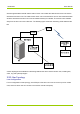
User Manual Introduction 1. Introduction 1.1 Product Description DS-9300 Digital Repeater ("DS-9300") is the new generation of repeater developed by Hytera. Using optical fibers to transmit signal, DS-9300 effectively makes up for the signal decline between base stations (BSs) and radios. Featuring low transmission loss and easy wiring, DS-9300 delivers long distance transmission of multicarrier signals and strong and dynamic signal coverage.
Introduction User Manual wireless signal between the BS and the radios. Donor unit includes the cable-access donor unit and the wireless-access donor unit. The cable-access donor unit is mounted into a 19-inch rack at the BS location while the wireless-access donor unit can be installed remotely from the BS. The remote unit is installed away from the donor unit over a fiber link. The following figure shows the networking of DS-9300 and the BS.
User Manual Introduction 0 0 Remote Unit 1 0 1 0 Remote Unit 1 1 2 0 Remote Unit 1 2 3 0 Remote Unit 1 3 Donor Unit 0 Remote Unit 1 0 Remote Unit 1 Donor Unit High Configuration For high configuration of star topology, each SFP port of the donor unit can connect to up to eight remote units, while one donor unit can connect to at most 16 remote units (N≤16). 1.3.
Introduction User Manual High Configuration For high configuration of ring topology, at most two rings can be formed on the donor unit, with each ring can connect to up to eight remote units (N≤8). 1.3.4 Hybrid Topology Low Configuration For low configuration of hybrid topology, each SFP port of the donor unit can connect up to four remote units, while one donor unit can connect to at most four remote units.
User Manual Introduction Specifications No. Item Downlink Uplink 5 MHz (operating bandwidth) 2 Channel Bandwidth 25 kHz 3 Channel Capacity 1–8 4 Max. Output Power 5W 5 1W Cable-access: 50 dB±3 dB±3 dB dB Max. Gain Wireless-access: 95 Gain Adjustment Range/Step 7 Gain Adjustment Error Wireless-access: 90 dB± 3 dB dB±3 dB 6 Cable-access: 45 30 dB/1 dB ≤1 dB@ gain of 0–20 dB ≤1.5 dB@ gain of 21–30 dB 8 9 Noise Figure Wireless-access: ≤5 dB Max.
Introduction User Manual Specifications No. Item Downlink Uplink band edge In-band 16 Intermodulation ≤–40 dBc@RBW3 kHz 8 CH 75 kHz Carrier Spacing ≤–45 dBc@RBW3 kHz 2 CH 75 kHz Carrier Spacing Attenuation Out-of-band (2.5 ≤–36 dBm/100 kHz@9 kHz to 1 GHz MHz away from the band edge) ≤–30 dBm/1 MHz@1 GHz to 12.
User Manual Introduction Specifications No.
Packing List User Manual 2. Packing List Please unpack carefully and check that all items listed below are received. If any item is missing or damaged, please contact us or your dealer. 2.1 Cable-access Donor Unit Item Qty. Item Qty. Main Unit 1 Cable Kit 1 Packing material for 19-inch Rack 1 Optical Cable Kit 1 Square Nut Kit 4 Power Cord 1 Crown Screw 4 Documentation Kit 1 2.2 Wireless-access Donor Unit Item Qty. Item Qty.
User Manual Getting Started 3. Getting Started 3.1 Appearance DS-9300 adopts modular design. For the wireless-access donor unit and the remote unit, its LED indicators and connectors are provided on the front and rear panels of the rack. The following figure shows the appearance of the remote unit. For the donor unit, its LED indicators are provided on the right side and connectors are provided on its bottom and right side. The following figure shows the appearance of the donor unit.
Getting Started User Manual 3.2 Donor Unit Interfaces 3.2.
User Manual Getting Started 3.2.2 Wireless-access Donor Unit 15 3 12 13 14 11 6 7 8 9 1 3.
Getting Started User Manual 3.4 Interface Description No. Label Meaning 1 / LED indicators 2 POWER Power switch 3 MANT Modem antenna connector Connector / See "3.6".
User Manual No. Getting Started Label Meaning location change Connector electric connector and door entry Description (generates an alarm upon illegal location change). Remote Unit: Monitors location change and the optical bypass switch. 15 BS RF interface N/F Connected to the donor antenna. 16 MS RF interface N/F Connected to the service antenna. 3.5 Interface Definition EXM Pin No. Signal Name Definition Remarks 1 INT1 External alarm 1 Closed: Alarm; Open: No alarm.
Getting Started Pin No. 4 User Manual Signal Name GND Definition Ground Remarks / LOC Pin No. Signal Name Definition Remarks 1 TX Data transmission Output. 2 RX Data receiving Input. 5 GND Ground / 3.6 LED Indicators The LED indicators on the donor and the remote units indicate the running status. LED Indicator ALM/VSWR COM PWR RUN CPRI 0 CPRI 1 CPRI 2 CPRI 3 Color Status Description Off The device is running well. Glowing or flashing The device malfunctions.
User Manual LED Indicator Getting Started Color Status Flashing or off Description Optical synchronization error.
Installation User Manual 4. Installation 4.1 Safety Information Before performing any operation, read the following precautions and operation instructions carefully to ward off potential risks. Local Laws and Regulations When installing a device, comply with the local safety laws and regulations. Power Supply Danger Direct contact or indirect contact (through moist objects) with the high voltage or mains electricity may result in fatal danger.
User Manual Installation Avoid dropping machinery and tools from the heights. Use strong ropes, hanging baskets or cable cars to deliver tools. Take sound safety actions such as wearing hamlets and safety belts properly. Do wear heat-retaining clothes for working in cold areas. Make sure the ladder is safe for use. Overload is strictly prohibited. The slant of the ladder is suggested to be 75°.
Installation User Manual 4.3.1 Environment Space Requirements It is recommended that the space of at least 200 mm be left between the product top and the ceiling, and 500 mm between the product bottom and the ground. For product installed at its back, the space of at least 500 mm should be left at the right side, and 200 mm at the left side of product; for product installed at its left side, the space of at least 200 mm should be left in front of product, and 200 mm in the back of product.
User Manual Installation The devices should be installed far away from electromagnetic interferences such as large electric devices. Outdoor Installation and Maintenance If the devices are installed outdoor, do not perform maintenance on extreme weathers such as storm, extreme temperature or high humidity. Grounding Requirements The ground wire must be connected before device installation, and be removed after the device is dismantled. Do not damage the grounding conductors.
Installation User Manual 4.4.1 Installation Parts The following figure shows the parts needed for installation, including the auxiliary fixture, back panel, latches and M6 screws. Auxiliary Fixture Captive Screw Back Panel M6 Screw Bolt 4.4.2 Installing the Product Installation on Pole You can install the product at its back or at its left side. The pole diameter should be between 60 mm to 114 mm. Installing at Back 1.
User Manual Installation 4. Insert the back panel into the auxiliary fixture and tighten the captive fasteners on the back panel of the product. Installing at Left Side Installing the product at left side and installing the product at back are almost the same. The only difference is that the back panel is secured to the left side rather than back of the product. The following figure shows the product installed at its left side.
Installation User Manual Installation on Wall You can install the product on a wall at the back or left side of the product. Installing at Back 1. Place the auxiliary fixture on the wall at the installation position and then mark the anchor points by using a marking pen. 2. Drill holes at the anchor points and then install the expansion bolt assemblies. 3. Fit the auxiliary fixture on the expansion bolts, and then tighten the bolts.
User Manual Installation 4. Secure the back panel onto the back of the product using four M6 screws. 5. Insert the back panel into the auxiliary fixture and tighten the captive fasteners on the back panel of the product.
Installation User Manual Installing at Left Side Installing the product at left side and installing the product at back are almost the same. The only difference is that the back panel is secured to the left side rather than back of the product. The following figure shows the product installed at its left side.
User Manual Installation 4.4.3 Cabling Cabling Requirements Lay out cables according to requirements to reduce interference between them. Safety Requirements Lay out cables away from sharp objects or jagged walls, or protect cables using conduit. Lay out cables away from heat sources, or add heat-insulation materials between cables and heat sources. Requirements for Binding Cables Bind same cables together. Bind cables securely and neatly, without damaging the cable jackets.
Installation User Manual Cover idle optical fiber connectors with protective caps.
User Manual Installation One end (at DS-9300 device) Other end Cable Connector Power Cable Round Electric Connector Optical Fiber SFP/SFP+ Monitoring 8-pin/1-pin Aviation Cable Connector Connected to …… Connected to …… AC Interfaces External Power Supply CPRI 0–1 Interfaces Optical Fiber Network EXM/LCT Interfaces External Monitoring Device Cabling Guide Cable-access Donor Unit 29
Installation User Manual Wireless-access Donor Unit Remote Unit Installing the Grounding Cable 1. According to the route, make a grounding cable with proper length, and install ring terminals at both ends of the cable.
User Manual Installation The metal wires must be completely sealed, as shown in the figure below. 2. Connect one end of the cable to the ground connector at bottom of DS-9300 and the other end to the grounding bar. 3. Attach labels or tags to the installed cable. Installing the RF Antenna 1. Remove protective caps from the antenna connector. 2. Connect the male end of the RF cable to the BS interface of the donor unit or the MS interface of remote unit and tighten the connector using the torque wrench.
Installation User Manual bottom to top, top to bottom, and bottom to top again. Cut off the tape after the three-layer is done. Tighten the tape at each layer to ensure waterproof. c. Wrap three-layer PVC insulation tape over the waterproof tape. Starting from 30 mm from the bottom of the waterproof tape, wrap the three-layer PVC insulation tape in the same method as introduced in step b. d. Bundle cable ties at 3–5 mm from both ends of the tape. 5.
User Manual Installation Procedure of installing the optical fiber is described as follows: 1. Connect the optical module to the SFP connector of DS-9300 device, as shown in the following figure. Note DS-9300 device adopts a dual-fiber single mode optical module with a transfer rate of 1.25 Gbps, a wavelength of 1,310 nm and a communication distance of 20 km. 1 2 3 a. Rotate the bail clasp latch down. b. Insert the optical module into the SFP connector. c. Rotate the bail clasp latch back. 2.
Installation User Manual 3. Lay out the cable according to design requirements and fix the cable with cable ties. 4. Attach labels or tags to the installed cable. 4.5 Post-installation Check 4.5.1 Checking the Installation Check the cables according to the table below. No. 1 Item The device is installed by strictly following the design draft. The installing position meets space requirements with maintenance space reserved. 2 The device is securely installed.
User Manual Installation If the RUN indicator flashes green and the ALM indicator is off, the status of DS-9300 device is normal.
Power On and Power Off User Manual 5. Power On and Power Off 5.1 Powering On Toggle the power switch on DS-9300 device to the ON position to power it on. Wait a few minutes and check the status of LED indicators. 5.2 Powering Off Toggle the power switch on DS-9300 device to the OFF position to power it off.
User Manual Debugging 6. Debugging Use the Product Support Software (PSS) to configure and upgrade the DS-9300 device. 6.1 Preparation Before debugging, prepare the PSS tool, and connect the device to the computer. You can debug the device either locally through the cable or IP connection, or remotely through IP connection. The default IP address of the device is 192.168.1.100; the IP address of the computer must be set to the same network segment, 192.168.1. X (X cannot be 100).
Debugging User Manual 2. Click Project, select DS_9300_CUSTOMER and click Lock. A message indicating locking database succeeded will appear in the message pane. 3. Select Ethernet tab, set the Destination and Port and click Connect. Note For debugging through the serial cable, select the Serial tab, set the Serial and Baudrate (115200) and click Connect. 4. Click Scan and the following window appears. 5. Select devices you want to display on the PSS and click OK.
User Manual Debugging 6.2.1 Querying Parameters To manually query parameters of the selected device, click Query Parameter. If you click Auto Query, PSS will query all the parameters of the selected device every two seconds. In the Scan list, click on the device and check Select All. Click Query Parameter, the parameter values will be displayed in Status. Note To query a specific parameter, check the parameter name and click Query Parameter.
Debugging User Manual Note For remote units, set the Downlink Output Under-power Threshold 10 dBm less than the actual output power in most cases. b. Select Real-time Sampling tab, and view the Downlink Input Power Level. The value of this parameter should be around -13 dBm for a cable-access donor unit, and -58 dBm for a wireless-access donor unit.
User Manual Debugging d. Select the Alarm Status tab, and turn on all switches if a repeater management system (RMS) is configured. When an alarm is generated, it will be alerted in red font and needs handling. 2. Click Setting, the result will be displayed in the message pane. Note To restore the factory settings, click Factory Reset. 6.2.3 Upgrade PSS allows you to upgrade the main program of the monitor board and the main program and FPGA of the digital board. 1. In the Upgrade area, click Load. 2.
Debugging User Manual Note If the upgrade fails or you want to roll back to the former version, perform the upgrade using the old upgrade file. 6.2.4 Exporting the Logs PSS allows you to export the operation logs. 1. In the Log area, click Path. 2. Specify the storage path and click Start.
User Manual System Maintenance 7. System Maintenance 7.1 Care and Cleaning To guarantee optimal performance as well as a long service life of the product, please follow the tips below. Caution Be sure to turn off the product before cleaning. Product Care Attach the connector cover with waterproof plug when the connector is not in use. Do not pierce, strike, throw or scrape the product. Keep the product away from substances that can corrode the circuitry. Keep the device dry.
System Maintenance User Manual Regularly check and record the working status and main parameters such as receiving signal level, output noise level, and downlink output power. Check whether the coverage meets the requirements. Check whether the monitoring system works properly. Check whether the signs and labels on the devices are complete. If the device malfunctions, return it for repair. 7.
User Manual System Maintenance Alarm Information Solution downlink output power) 7.4 Troubleshooting Phenomena Possible Cause Solution Connect the power cable The device fails to be The power cable is not connected, or the powered on. contact with the socket is loose. The RUN indicator glows The unit is powered, but a module is Troubleshoot or replace the green solidly. faulty. faulty module. properly and ensure good contact. Check whether the power cable The RUN indicator is off.
Appendix: Parameters User Manual 8. Appendix: Parameters Take the donor unit as example. Device Information Parameter Configuration Electronic Serial Number Enter up to 10 characters, including digits (ESN) and letters. Monitor Version Keep the default value unchanged. FPGA Version Keep the default value unchanged. Application Version Keep the default value unchanged. Remarks Serial number of the device. Version of the monitor board. Version of FPGA in the digital modules.
User Manual Appendix: Parameters home BS ID. The donor unit is 0; the range for remote Device No. unit in low configuration is 1 to 4; the range for remote unit in high configuration is 1 to 16. Device number of corresponding donor or remote units. The range is 0 to 255. Manufacturer ID 1: Hytera / 2: Reserved The range is 1 to 13.
Appendix: Parameters User Manual Latitude or West Longitude. This parameter is subject to actual Device Latitude requirements. Negative number represents South / Latitude or West Longitude. The range is 0 to 2. Communication Method for Reporting Alarms 1: SNMP / 2: Reserved Monitor Center IP Address Monitor Center Port No. Site Description This parameter is subject to actual IP address of the RMS Monitor requirements. Center. The range is 0 to 65535.
User Manual Actual Number of Carriers Downlink Input Power Level (dBm) Uplink Output Power Level (dBm) Appendix: Parameters The range is 0 to 32. Actual number of channels the device has opened. The range is –110 to 10. / The range is –110 to 50. / 0: Offline Whether the remote unit is 1: Online online. Remote Unit Online Switch Remote Unit Connection 0: Not connected Whether a remote unit is Indicator 1: Connected connected.
Appendix: Parameters Inspection Report Troubleshooting Report User Manual 1: Report 1: Report 1: Report Report 0: Do not report threshold Uplink/Downlink Squelch Threshold (dBm) / The range is –110 to 50. / 0: Enable Switch 1: Disable Remote Unit Delay 0: Enable Auto-compensation Switch 1: Disable (dB) Downlink Digital Attenuation (dB) / The range is 0 to 65535.
User Manual Appendix: Parameters 0: Disable Channel Switch / 1: Enable Alarm Status Parameter Master-Slave Monitoring Link Fault Alarm Enable Power Supply Disconnection Alarm Enable Power Supply Fault Alarm Enable Downlink Input Over-power Alarm Enable Uplink Output Over-power Alarm Enable Uplink Local Oscillator Unlock Alarm Enable Downlink Local Oscillator Unlock Alarm Enable Remote Digital Module Fault Alarm Enable Downlink LNA Fault Alarm Enable Optical Receiving Alarm Enable Optical
Appendix: Parameters User Manual 1: Enable Master-Slave Monitoring Link Fault Alarm Power Supply Disconnection Alarm Power Supply Fault Alarm Downlink Input Over-power Alarm Uplink Input Over-power Alarm Downlink PA Over-current Alarm Uplink Local Oscillator Unlock Alarm Downlink Local Oscillator Unlock Alarm Remote Digital Module Fault Alarm Downlink LNA Fault Alarm Optical Receiving Alarm Optical Transmission Alarm 0: Normal 1: Fault 0: Normal 1: Fault 0: Normal 1: Fault 0: