
Instructions / Assembly
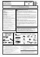


Installation Instructions
7
DRYER E;HA8ST TO RIGHT /EFT
OR BOTTOM CABINET
WARNING BEFORE PERFORMING
THIS E;HA8ST
INSTA//ATION BE S8RE
TO DISCONNECT THE DRYER FROM ITS
E/ECTRICA/ S8PP/Y PROTECT YO8R
HANDS AND ARMS FROM SHARP
EDGES WHEN WORKING INSIDE THE
CABINET BE S8RE TO WEAR G/O9ES
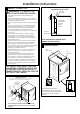
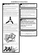
Note: Only 4” round rigid metal ducting allowed inside
dryer.
TAB /OCATION
Detach and remove the bottom, right or left side knockout
as desired. Remove the screw inside the dryer exhaust duct
and save. Pull the duct out of the dryer.
REMOVE
SCREW
AND SAVE.
REMOVE
DESIRED
KNOCKOUT
(ONE ONLY).
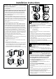
ADDING NEW D8CT
ADDING E/BOW AND D8CT FOR
E;HA8ST TO /EFT SIDE OF CABINET
3UHDVVHPEOHµHOERZZLWKµGXFW:UDSGXFWWDSH
DURXQGMRLQW
,QVHUWGXFWDVVHPEO\HOERZ¿UVWWKURXJKWKHVLGH
RSHQLQJDQGFRQQHFWWKHHOERZWRWKHGU\HULQWHUQDO
GXFW
CA8TION: Be sure not to pull or damaJe
the electrical Zires inside the dryer Zhen insertinJ the
duct
$SSO\GXFWWDSHDVVKRZQRQWKHMRLQWEHWZHHQWKH
GU\HULQWHUQDOGXFWDQGWKHHOERZ
Cut the duct as shown and keep portion A.
9"
AB
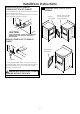
FIXING HOLE
Through the rear opening, locate the tab in the middle of
the appliance base. Lift the tab to about 45º using a flat
blade screwdriver.
BEND TAB
UP 45
o
Reconnect the cut portion (A) of the duct to the blower
housing. Make sure that the shortened duct is aligned with
the tab in the base. Use the screw saved previously to secure
the duct in place through the tab on the appliance base.
LEFT SIDE
EXHAUST
PORTION "A"
FIXING
HOLE
EXHAUST CAN
BE ADDED TO
LEFT OR RIGHT SIDE
DUCT
TAPE
DUCT
TAPE
CA8TION:
Internal duct joints must be
secured Zith tape otherZise
they may separate and cause
a safety ha]ard
GARAGE INSTA//ATION IF A//OWED
BY /OCA/ CODES
'U\HUVLQVWDOOHGLQJDUDJHVPXVWEHHOHYDWHGLQFKHV
FPDERYHWKHÀRRU
2