
Installation Guide
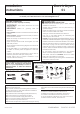


Installation Instructions
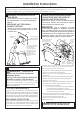
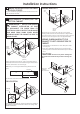
CONNECTING DRYER USING 3-WIRE
CONNECTION
3-wire Connection
Not for use in Canada.
DO NOT use for Mobile Home Installations.
NOT for use on new construction.
NOT for use on recreational vehicles.
NOT for use in areas where local codes prohibit grounding
through the neutral conduction.
1. 7XUQ RȺ WKH FLUFXLW EUHDNHUV DPS RU UHPRYH WKH
dryer’s circuit fuse at the electrical box.
2. Be sure the dryer cord is unplugged from the wall.
5HPRYHWKHSRZHUFRUGFRYHUORFDWHGDWWKHORZHUEDFN
4. ,QVWDOOLQ8/UHFRJQL]HGVWUDLQUHOLHIWRSRZHUFRUG
entry hole. Bring power cord through strain relief.
5. Connect power cord as follows:
A. Connect the 2 hot lines to the outer screws of
the terminal block (marked L1 and L2).
B. Connect the neutral (white) line to the center of
the terminal block (marked N).
6. Be sure ground strap is connected to neutral (center)
terminal of block and to green ground screw on cabinet
UHDU7LJKWHQDOOWHUPLQDOEORFNVFUHZVVHFXUHO\
7. Properly secure power cord to strain relief.
8. 5HLQVWDOOWKHFRYHU
3
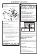
EXHAUST INFORMATION
WARNING - IN CANADA AND IN THE
UNITED STATES, THE REQUIRED EXHAUST
DUCT DIAMETER IS 4 IN (102mm). DO NOT
USE DUCT LONGER THAN SPECIFIED IN THE
EXHAUST LENGTH TABLE.
8VLQJH[KDXVWORQJHUWKDQVSHFL¿HGOHQJWKZLOO
• Increase the drying times and the energy cost.
5HGXFHWKHGU\HUOLIH
$FFXPXODWHOLQWFUHDWLQJDSRWHQWLDO¿UHKD]DUG
The correct exhaust installation is YOUR
RESPONSIBILITY. Problems due to incorrect installation
are not covered by the warranty.
5HPRYHDQGGLVFDUGH[LVWLQJSODVWLFRUPHWDOIRLOWUDQVLWLRQ
duct and replace with UL listed transition duct.
The MAXIMUM ALLOWABLE duct length and number of
bends of the exhaust system depends upon the type of
duct, number of turns, the type of exhaust hood (wall cap),
and all conditions noted below. The maximum duct length
for rigid metal duct is shown in the table below.
EXHAUST LENGTH
4" DIA.
4"
4" DIA.
4" DIA.
2-1/2"
RECOMMENDED MAXIMUM LENGTH
Exhaust Hood Types
Recommended
No. of 90º
Elb ows
Rigid
Metal
Rigid
Metal
90 F eet
60 F eet
45 F eet
35 F eet
25 F eet
0
1
2
3
4
60 F eet
45 F eet
35 F eet
25 F eet
15 F eet
Use only for sho rt
run installations
EXHAUST SYSTEM CHECK LIST
HOOD OR WALL CAP
• Terminate in a manner to prevent back drafts or entry of
birds or other wildlife.
• Termination should present minimal resistance to the
H[KDXVWDLUÀRZDQGVKRXOGUHTXLUHOLWWOHRUQRPDLQWHQDQFH
to prevent clogging.
• Never install a screen in or over the exhaust duct. This could
cause lint build up.
• Wall caps must be installed at least 12 in. above ground
level or any other obstruction with the opening pointed
down.
SEPARATION OF TURNS
For best performance, separate all turns by at least 4 ft.
of straight duct, including distance between last turn and
exhaust hood.
TURNS OTHER THAN 90º
• One turn of 45º or less may be ignored.
• Two 45º turns should be treated as one 90º turn.
• Each turn over 45º should be treated as one 90º turn.
• For every extra 90° elbow, reduce the allowable vent system
length by 10 ft.
• Two 45° elbows will be treated like one 90° elbow.
• For the side exhaust installations, add one 90° elbow to the
chart.
• The total vent system length includes all the straight portions
and elbows of the system (transition duct included).
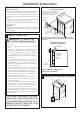
WARNING: NEVER LEAVE THE
COVER OFF OF THE TERMINAL BLOCK.
Screws
(2)
Hot
Wire
µ8/
5HFRJQL]HG
6WUDLQ5HOLHI
$:*PLQLPXPFRSSHUFRQGXFWRUVRU9$SRZHUVXSSO\
cord kit marked for use with dryers and provided with closed loop or
spade terminals with upturned ends (not supplied).
Fuse
Hot
Wire
Neutral
(white)
Strain
5HOLHI
Bracket
Cover
Screw
If required, by local code, install external ground (not provided) to
grounded metal, cold water pipe, or other established ground determined
by a qualified electrician.
Green Ground Screw
& Ground Strap