
Health safety & Environmental


INSTRUCTIONS FOR THE FITTER
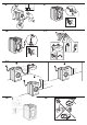
Mounting the wooden panel onto the door
and inserting the machine into cabinets:
In the case where the machine must be shipped
for nal installation after the wooden panel has
been mounted, we suggest leaving it in its ori-
ginal packaging. The packaging was designed
to make it possible to mount the wooden panel
onto the machine without removing it comple-
tely (see gures below).
The wooden panel that covers the face of the ma-
chine must not be less than 13 mm in thickness
and can be hinged on either the right or left. For
the sake of practicality when using the machine,
we recommend that the panel be hinged on the
same side as the door for the machine itself - the
left.
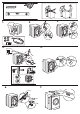
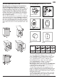
Door Mounting Accessories (Fig. 1-2-3-4-5).
Fig. 1
N° 2 Hinges
N° 1 Magnet N° 1 Magnet plate
N° 1 Rubber plug
N° 2 Hinge Supports
N° 4 Spacers
Fig. 2
Fig. 3 Fig. 4
Fig. 5
Fig. 4/B
Type A B C D
Lenght 13 mm 25 mm 20 mm 7 mm
- No. 6 type A self-threading screws, l =13 mm.
- No. 2 type B metric, countersunk screws, l =25;
for fastening the magnet plate to the cabinet.
- No. 4 type C metric screws, l =20 mm; for
mounting the hinge supports to the cabinet.
- No. 4 type D metric screws, l =7 mm; for
mounting the hinges on the supports.
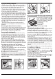
Mounting the Parts onto the Face of the Machine.
- Separate hinge supports from the hinges by
removing the screws type D.
- Fit the hinge supports to the appliance front
panel, positioning the hole marked with an arrow
in g. 1 so that it is on the inner side of the front
panel. Fit a spacer (g. 4/B) between the surfaces
using type C screws.
- Fit the magnet plate at the top of the opposite
side, using type B screws to x two spacers (g.
4/B) between the plate and the surface.
EN
A
B
C
D
E
Tur seite