
Instruction for Use


4
consumption and ensure a longer life for your appliance.
CONNECTION WITH A HOSE
Make the connection using a gas hose that complies with require-
ments set forth by the current standards. The inner diameters of
the pipe are as follows:
- 8 mm for liquid gas;
- 13 mm for methane.
When installing the hose, remember to take the following pre-
cautions:
•
No part of the hose must come into contact with parts whose
temperature exceeds 50°C;
•
The length of the hose should be less than 1500 mm;
•
The hose should not be subject to twisting or pulling, and
should not have bends or kinks;
•
The hose should not touch objects with sharp edges, corners
or moving parts, and it should not be crushed;
•
The full length of the hose should be easy to inspect in order
to check its condition.
Check that the hose fi ts fi rmly into place at the two ends and
fi x it with clamps complying with current standards. If any of the
above recommendations can not be followed, fl exible metal
pipes should be used.
If the cooker is installed in compliance with the require-
ments for class 2, subclass 1, it is highly recommended
that the gas connection be made with a fl exible metal pipe
in compliance with current safety standards.
CONNECTING A FLEXIBLE, JOINTLESS, STAINLESS
STEEL PIPE TO A THREADED ATTACHMENT
Remove the hose holder fi tted on the appliance. The gas supply
pipe fi tting is a threaded 1/2 gas cylindrical male attachment. Use
only pipes and seals that comply with
current National Regulations. The full length of the pipe when
installed must not exceed 2000 mm. After the connection has
been made, make sure that the fl exible metal pipe does not come
into contact with moveable parts and that it is not crushed.
CHECKING THE SEAL
Important:
Once the installation has been completed, check to
make sure that the seals on all the connections are tight, using
a soapy solution (never a fl ame).
CONNECTING THE POWER SUPPLY CORD TO THE
MAINS
Install a normalised plug corresponding to the load indicated on
the data plate. When connecting the cable directly to the mains,
install an omnipolar circuit-breaker with a minimum contact open-
ing of 3 mm between the appliance and the mains. The omnipolar
circuit breaker should be sized according to the load and should
comply with current regulations (the earth wire should not be
interrupted by the circuit breaker). The supply cable should be
positioned so that it does not reach a temperature of more than
50°C with respect to the room temperature, along its length.
Before making the connection, check that:
•
The limiter valve and the home system can support the ap-
pliance load (see data plate);
•
The mains are properly earthed in compliance with current
safety standards and regulations;
•
There is easy access to the socket and omnipolar circuit
breaker, once the hob has been installed.
N.B
.: Never use reducers, adaptor
s or shunts since they can
cause heating or burning.
CONVERTING THE COOKER TO DIFFERENT TYPES OF
GAS
In order to convert the cooker for use with a type of gas different
than the one for which it was factory set (indicated on the label
attached to the lid), the following steps must be taken:
A)
REPLACE THE HOSE HOLDER
•
Replace the hose holder mounted on the appliance with that
supplied in the bag of “cooker accessories.”
Important: The hose holder for liquid gas is marked 8, the hose
holder for methane is marked 13. In any case, always use a
new sealing gasket.
B
)
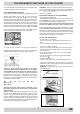
REPLACING THE BURNER NOZZLES ON THE HOB
•
Remove the grids, the burner caps (A) and the burner
bodies (B).
•
Unscrew and remove the nozzles in the bottom of each
nozzles holder (C), using a 7 mm socket wrench.
•
Replace the nozzles in accordance with table 1
“Specifi cations of burners and nozzles”), tighten and screw
right down.Check that the system is gas-tight.
•
Replace the burners, the burner caps and the grids.
A
B
C
C)
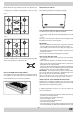
SETTING HOB BURNER MINIMUM LEVELS
If the cooker is to work on bottled gas (butane/propane), the
tap by-pass must be screwed right down.The cooker may be
equipped with type A taps, with by-pass inside (accessed by
inserting a small screwdriver into the rod) or type B taps, with
by-pass on the outside on the right (accessed directly). See
fi gure 9.
If the cooker is to work on natural gas, proceed as follows for
both types of tap:
- Ignite the burner at maximum fl ame;
- pull off the knob, without using a lever against the control panel,
which might be damaged;
- access the by-pass with a small screwdriver and back off by
about 3 turns (turning the screwdriver anti-clockwise);
- turn the tap rod anti-clockwise again until it stops: the burner
will be at maximum fl ame;
- screw the by-pass slowly back in, without pushing the screw-
driver, until the fl ame has apparently shrunk to 1/4 of the
maximum size, checking that it is suffi ciently stable even in
quite strong draughts.
9
A
A
B
B
B
D
)
SETTING OVEN BURNER MINIMUM LEVELS
If the cooker is to work on bottled gas (butane/propane), the
thermostat by-pass must be screwed right down.
If the cooker is to work on natural gas, proceed as follows:
- Remove the oven bottom (loosen the screw to remove the