
Instruction for Use


6
GB
Connecting the supply cable to the electricity mains
The appliance must be directly connected to the mains
using an omnipolar switch with a minimum contact
opening of 3 mm installed between the appliance and
the mains. The switch must be suitable for the charge
indicated and must comply with current electrical
regulations (the earthing wire must not be interrupted by
the switch). The supply cable must be positioned so that
it does not come into contact with temperatures higher
than 50°C at any point.
Before connecting the appliance to the power supply,
make sure that:
• The appliance is earthed and the plug is compliant with
the law.
• The socket can withstand the maximum power of the
appliance, which is indicated by the data plate.
• The voltage is in the range between the values
indicated on the data plate.
• Do not use extension cords or multiple sockets.
! Once the appliance has been installed, the power supply
cable and the electrical socket must be easily accessible.
! The cable must not be bent or compressed.
!
The cable must be checked regularly and replaced
by authorised technicians only.
! The manufacturer declines any liability should these
safety measures not be observed.
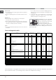
TABLE OF CHARACTERISTICS
Oven dimensions
(HxWxD)
32x43.5x40 cm
Volume
57 l
Useful
measur ements
relating to the
oven
compartment
width 42 cm
depth 44 cm
height 8.5 cm
Voltage and
frequency
see data plate
ENERGY LABEL
Directive 2002/40/EC on the label
of electric ovens. Standard EN
50304
Declared energy consumption for
Forced convection Class – heating
mode: ECO
EC Directives: 2006/95/EC dated
12/12/06(Low Voltage) and
subsequent amendments -
2004/108/EC dated 15/12/04
(Electromagnetic Compatibility)
and subsequent amendments -
90/396/EEC dated 29/06/90 (Gas)
and subsequent amendments -
93/68/EEC dated 22/07/93 and
subsequent amendments -
2002/96/EC.
1275/2008 (Stand-by/Off mode)
ECO
•the power supply system has an efficient earthing
connection which complies with the provisions of cur-
rent regulations and the law;
•there is easy access to the socket or the omnipolar
circuit-breaker once the cooker has been installed.
! Do not use reducers, adapters or shunts as these co-
uld cause heating or burning.
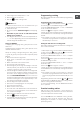
Anti-tilt Wall Bracket
To install the Anti-Tilt Wall Bracket:To install the Anti-Tilt Wall Bracket:To install the Anti-Tilt Wall Bracket:
! In order to prevent accidental
tipping of the appliance, for
example by a child climbing onto
the oven door, the supplied "anti-
tilt bracket" MUST be installed!
1. Fit the cooker between the cabinets and adjust the
height of the appliance (if necessary) by means of
adjustable feet.
2. Take out the lower compartment.
3. On the wall behind the cooker draw a line along
the horizontal edge A and then along the vertical edge
B so that the lines cross (see figures below).
4. Pull the cooker out of the space between cabinets
and attach the Anti-tilt Bracket with (its shorter arm
to the wall) in the position shown in the picture below:
37 mm left and 5 mm up from the crossing of the lines
A and B, inserting two bolts of 6mm diameter in the
holes: x and y.
x
y
5. Place the cooker back between the cabinets so that
the Anti-Tilt Wall Bracket fits inside the appliance.
6. Reinsert the lower compartment.
! The Anti-Tilt Wall Bracket may be installed both on the
left and on the right handside of the cooker.
! The Anti-Tilt Wall Bracket may be installed both on the
left and on the right handside of the cooker.
! The Anti-Tilt Wall Bracket may be installed both on the
left and on the right handside of the cooker.