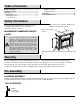
Model # WSFP42ECHD-28 # WSFP42ECHD-29 # WSFP42ECHD-30 OMSID # 301353160 OMSID # 301353179 OMSID # 301538219 ASSEMBLY INSTRUCTIONS Coloreidge 42 in. Mantel Console with Infrared Electric Fireplace Questions, problems, missing parts? Before returning to the store, call Home Decorators Collection Customer Service 8 a.m. - 7 p.m., EST, Monday-Friday 9 a.m. - 6 p.m., EST, Saturday 1-800-986-3460 HOMEDEPOT.
Table of Contents Table of Contents .......................................................... 2 Safety Information ......................................................... 2 Warranty ......................................................................... 2 Pre-Assembly ................................................................ 2 Planning Assembly ..................................................... 2 Tools required ............................................................
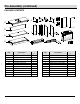
Pre-Assembly (continued) HARDWARE INCLUDED NOTE: Hardware not shown to actual size. AA LL UU BB CC MM DD EE FF NN OO PP MAXIMUM HH MAXIMUM LOAD II MAXIMUM 50 LOAD LB JJMAXIMUM (22.7 50 LOAD LB kg) MAXIMUM (22.7 50 LOAD LB kg)(22 M 50 KK GG QQ TT MAXIMUM RR LOAD SS 50 LB MAXIMUM (22.750 kg) 50 MAXIMUM LOAD LBLOAD (22.7 M kg MAXIMUM MAXIMUM MAXIMUM LOAD 50 LB LOAD (22.750kg) LB (22.
Pre-Assembly (continued) PACKAGE CONTENTS E F H G A O P S T B I J K L C D M Part Description N Q R Quantit y Part Description Quantit y A Top panel 1 L Right lower side panel 1 B C D E F G Back panel Center shelf Base Left upper side panel Barrister door left support Barrister door right support 1 1 1 1 1 1 M N O P Q R Barrister door Center crossbar Left Upper front molding Right Upper front molding Support Adjustable shelf 1 2 1 1 2 2 H I J K Right upper side panel Lowe
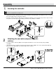
Assembly 1 Screwing the cam bolts NOTE: Do not fully tighten all bolts until you finish assembling all parts. Once assembled, go back and fully tighten all bolts. This will make the assembly easier. □ □ Unpack the unit and confirm that you have all the hardware and required parts. Assemble the unit on a carpeted floor or the empty carton to avoid any scratches.
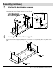
Assembly (continued) 3 Combining the upper moldings and side panels NOTE: Refer to the dowel and cam lock assembling guide drawings in this step for further clarification on how to properly glue in the wooden dowels and install cam locks. Apply this method whenever instructed to install wood dowels and cam locks. □ □ Glue one wood dowel (CC) into the inner hole of the left upper side panel (E) and attach it to the left upper front molding (O) by engaging two cam locks (AA) as shown.
Assembly (continued) 5 □ Attaching the barrister door supports Glue four wood dowels (CC) into the inner holes on the upper edge of the barrister door supports (F and G) and attach them to the top panel (A) by engaging four cam locks (AA). G AA F CC H A E 6 □ Securing the barrister door supports Fasten the barrister door supports (F and G) to the back stretcher of the top panel (A) with two long wood screws (DD). P G O A DD F DD 7 HOMEDEPOT.
Assembly (continued) 7 □ □ □ Installing the center crossbar and the center shelf Align and attach the center crossbar (N) to the center shelf (C) with two wood dowels (CC) and three cam locks (AA). Glue six wood dowels (CC) into the inner holes at the bottom edge of the upper side panels (E and H) and front moldings. Properly position the center shelf (C) onto the inserted wood dowels (CC) and secure in place by engaging six long wood screws (DD).
Assembly (continued) 9 □ Attaching the lower back panels Align and attach lower back panels (I) to the lower side panels (K and L) with two wood dowels (CC) and two long wood screws (DD) per panel. J J L CC DD K I CC I DD DD 10 DD Installing the lower side panel assemblies □ Glue eight wood dowels (CC) into the top inner holes of both lower side panel assemblies. □ Align the large holes on the center shelf (C) with the inserted wood dowels (CC) and press them together.
Assembly (continued) 11 □ Attaching the center crossbar Align and attach the remaining center crossbar (N) to the base (D) with two wood dowels (CC) and three cam locks (AA). N CC AA D 12 □ Installing the supports Align and attach the supports (Q) to the base (D) with two wood dowels (CC) and two cam locks (AA) in each, as shown.
Assembly (continued) 13 □ Installing the base assembly Align and attach the base assembly to the lower side panel assemblies with eight wood dowels (CC) and eight cam locks (AA). J L I J K I D CC 14 □ Securing the base Insert four long wood screws (DD) through the drilled holes on the base (D) and securely screw into the lower side panels (K and L). J L J I D K DD I DD DD DD 11 HOMEDEPOT.COM/HOMEDECORATORS Please contact 1-800-986-3460 for further assistance.
Assembly (continued) 15 Installing the metal plate □ Flip the assembled unit around at its front edges. Secure the middle crossbars (N) to both lower front panels (J) by attaching four metal plates (KK) at the joints, using two short wood screws (EE) in each, as shown. EE KK J N N J 16 □ Attaching the back panel Pick up the back panel (B) and align the drilled holes against the upper long edge with the pilot holes on the back stretcher of the top panel (A).
Assembly (continued) 17 □ □ Attaching the bottom pivot hinges Using the pilot holes as a guide, attach the left bottom pivot hinge (PP) to the left door (S) with two short wood screws (EE) as shown. Make sure that the pivot pin runs against the edge. Repeat the same procedure to attach the right bottom pivot hinge (QQ) to the right door (T). EE EE QQ S T PP 18 Installing the left door □ □ □ □ Stand the assembled unit upright.
Assembly (continued) 19Installing the right door □ Repeat the same procedure with the right door (T). PP T PP PP EE T 20 Installing the adjustable shelves and cam lock covers □ □ Open the doors and insert four shelf supports (JJ) into the desired holes inside each side compartment. Make sure you place the four shelf supports in the same level so the shelf is not tilted. Rest the adjustable shelves (R) onto the shelf supports (JJ).
Assembly (continued) 21 □ □ Installing the hooks and knob Using the pilot holes as a guide, fasten two hooks (OO) to the upper corners of the barrister door (M) with four short wood screws (EE). Attach one knob (SS) to the front side of the barrister door (M) with the knob bolt (TT).
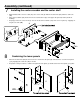
Assembly (continued) 23 □ Installing the fireplace insert Lift the fireplace insert carefully into the back of the assembled mantel and center it in the opening. DO NOT drag the insert across the bottom panel (D) as it may scratch the unit. Q Q 24 Attaching the L-shaped metal braces □ Using the pilot holes as a guide, align and attach two L-shaped metal braces (LL) to the supports (Q) by screwing two short pan head screws (HH).
Assembly (continued) 25 Installing the acrylic stopper □ □ Remove the paper backing of acrylic stopper (RR), then properly align the acrylic stopper into the cut-out on the acrylic stopper template on the front of the top panel (A). Press down on the acrylic stopper to help adhesion. At the back of the top panel (A), carefully pull out the thumb tacks to remove the acrylic stopper template.
Care and Maintenance A Touch-up Pen has been provided to repair any small nicks or scratches that may occur during assembly or shipping. To clean and care for your furniture: □ Use a soft, clean cloth that will not scratch the surface when dusting. □ Use of furniture polishes is not necessary. Should you choose to use polishes, test first in an inconspicuous area. □ Using solvents of any kind on your furniture may damage the finish.
Questions, problems, missing parts? Before returning to the store, call Home Decorators Collection Customer Service 8 a.m. - 7 p.m., EST, Monday-Friday 9 a.m. - 6 p.m., EST, Saturday 1-800-986-3460 HOMEDEPOT.COM/HOMEDECORATORS Retain this manual for future use.