Item #1006148231 Model #1418FM-23-251 ASSEMBLY INSTRUCTIONS NORTHGLENN 36 IN INFRARED ELECTRIC FIREPLACE IN WHITE OAK Questions, problems, missing parts? Before returning to the store, call Home Decorators Collection Customer Service 8 a.m. - 7 p.m., EST, Monday - Friday, 9 a.m. - 6 p.m., EST, Saturday 1-800-986-3460 HOMEDEPOT.COM/HOMEDECORATORS THANK YOU We appreciate the trust and confidence you have placed in Home Decorators Collection through the purchase of this fireplace console.
Table of Contents Table of Contents. . . . . . . . . . . . . . . . . . . . . . . . . . . . . . . . . . . . 2 Safety Information. . . . . . . . . . . . . . . . . . . . . . . . . . . . . . . . . . . 2 Important Instructions. . . . . . . . . . . . . . . . . . . . . . . . . . . . . . . 2 Warranty. . . . . . . . . . . . . . . . . . . . . . . . . . . . . . . . . . . . . . . . . . . 5 Pre-Installation. . . . . . . . . . . . . . . . . . . . . . . . . . . . . . . . . . . . . . 6 Planning Installation . . . . . . . .
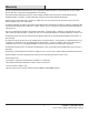
Safety Information (continued) WARNING: □ This appliance is hot when in use. To avoid burns, DO NOT let bare skin touch hot surfaces. Keep combustible material, such as furniture, pillows, bedding, papers, clothes and curtains at least 3 feet from this appliance and keep them away from the sides and rear. □ Extreme caution is necessary when any heater is used by or near children or individuals with disabilities and whenever the fireplace is left operating and unattended. □ DO NOT run cord under carpeting.
Safety Information (continued) Electrical Connection □ A 15-Amp, 120-volt, 60 Hz circuit with a properly grounded outlet is required. Preferably, the fireplace will be on a dedicated circuit as other appliances on the same circuit may cause the circuit breaker to trip or the fuse to blow when the heater is in operation. The unit comes standard with 6-ft. three-wire cord, exiting from the rear of the fireplace. DO NOT exceed the current rating of the current tap.
Warranty This item is warrantied by the manufacturer to be free of material and manufacturing defects for the time period of one year from the purchase date. This is subject to the following limitations and conditions: This mantel must be installed and operated in accordance with the installation instructions that were provided with the product. Unauthorized repairs or alterations, accidents, willful abuse and misuse of the product will nullify this warranty.
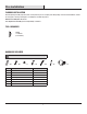
Pre-Installation PLANNING INSTALLATION Before beginning assembly of product, make sure all parts are present. Compare parts with package contents list and hardware contents list. If any part is missing or damaged, do not attempt to assemble the product. Estimated Assembly Time: 50 minutes. Tools Required for Assembly (not included): Phillips screwdriver. TOOLS REQUIRED Phillips screwdriver (not included) HARDWARE INCLUDED NOTE: Hardware not shown to actual size.
Pre-Installation (continued) PACKAGE CONTENTS A E C B H F I G D Part Description Quantity A Top 1 B Left Side Panel 1 C Left Front Panel 1 D Center Front Panel 1 E Right Front Panel 1 F Right Side Panel 1 G Base 1 H Insert 1 I Remote Control 1 7 HOMEDEPOT.COM/HOMEDECORATORS Please contact 1-800-986-3460 for further assistance.
Installation 1 Install front panel □ Set center front panel (D) down on a non-scratch surface. Insert four wooden dowels (AA) into holes on left and right sides of center front panel (D). Align the holes on center front panel (D) with the corresponding holes on left front panel (C) and right front panel (E), securing with two short screws (BB).
Installation (continued) 3 Install left and right panel □ Insert four wooden dowels (AA) into the holes on the back of the left front panel (C) and right front panel (E). Attach the left side panel (B) to the left front panel (C), secure with screwing three locknuts (CC) by Phillips screwdriver. Repeat for the right side panel (F).
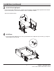
Installation (continued) 5 Screw the connecting rod □ Screw seven connecting rods (DD) into designated plastic bushings on the back of the top (A). Fully tighten with a Phillips screwdriver. DD A 6 Install top □ Insert four wooden dowels (AA) into the top outer holes on both side panels (B, F). Attach top (A), securing from underneath with screwing seven locknuts (CC) by Phillips screwdriver.
Installation (continued) 7 Remove insert brackets □ From behind the assembly, remove the preassembled insert brackets from the middle area. Save brackets and screws for future use. 1 1 2 8 Install insert NOTE: Before proceeding to the next step, with the help of another person, move the mantel close to the final desired location. DO NOT plug insert (H) into power outlet yet. CAUTION: DO NOT slide insert on top of wood to avoid scratching wood surface.
Installation (continued) 9 Re-install insert brackets □ Re-attach insert brackets with previously removed screws to secure insert (H). Assembly is now complete. With the help of another person, move the assembly to the final desired location. Once in final position, you may plug the insert (H) into the power outlet. 1 H 1 2 WARNING: You must install the tip restraint hardware to help prevent any accidents or damage to the unit.
Operating Instructions Control Panel Remote Control To use the remote control, first remove the plastic tab by gently pulling it out of remote control (I). Power Button □ Pressing the power button will turn ON or OFF the unit. □ When the unit is in ON mode, the power icon indicator light will be shown green and turn ON the heating level and flame brightness effect with the last settings. □ When the unit is in OFF mode, the power icon indicator light will be shown red.
Operating Instructions (continued) Temperature Mode □ The temperature mode controls the heater’s thermostat setting. □ Use Up arrow button or Down arrow button to scroll through the pre-set temperature setting. The temperature setting range is 65ºF (18ºC) to 90ºF (32ºC), HI (High) and OF (OFF). □ Hold down the Up arrow button and Down arrow button for 5 seconds to toggle between 5°F (3°C) increments and 1°F (1°C) increments when setting the temperature.
Care and Maintenance □ □ □ □ Tips for using touch-up pen (FF): For scratches, stroke in direction of scratch. For worn areas, stroke in the direction of wood grain. Rub excess colorant promptly with a soft cloth. □ lubrication. However, periodic cleaning/vacuuming of the fan/heater is recommended. Replacing the Remote Control Battery When the remote control (I) stops operating or its range seems reduced, it is time to replace the battery.
Troubleshooting Problem Possible cause Error E1 displayed on control panel. The overheat sensor has been engaged. Solution Unplug unit, wait 5-10 minutes, then the sensor will reset itself. Plug the unit back in and turn on the heater. If the problem persists, call customer service. NOTE: The other functions will work normally. Until the problem is solved, the error will only appear/sound when the heater button is pressed. Error E2 displayed on control panel.
Service Parts MODEL TYPE D A B E F C H G GG HH II BB Short Screw (X 2) AA Wooden Dowel (X 18) CC Locknut (X 13) DD Connecting Rod (X 13) EE Long Screw (X 6) Part I FF Touch-up Pen (X 1) Description Part # A Top 1418FM-23-251-TOP B Left Side Panel 1418FM-23-251-LEFT SIDE PANEL C Left Front Panel 1418FM-23-251-LEFT FRONT PANEL D Center Panel 1418FM-23-251-CENTER PANEL E Right Front Panel 1418FM-23-251-RIGHT FRONT PANEL F Right Side Panel 1418FM-23-251-RIGHT SIDE PANEL G B
Questions, problems, missing parts? Before returning to the store, call Home Decorators Collection Customer Service 8 a.m. - 7 p.m., EST, Monday - Friday, 9 a.m. - 6 p.m., EST, Saturday 1-800-986-3460 HOMEDEPOT.COM/HOMEDECORATORS Retain this manual for future use.