SKU #1009012720 Model #LDS-BF2002 USE AND CARE GUIDE VENTILATION FAN Questions, problems, missing parts, before returning to the store, call Hampton Customer Service 8 a.m. – 6 p.m., EST, Monday - Friday 1-855-HD-HAMPTON HOMEDEPOT.COM THANK YOU We appreciate the trust and confidence you have placed in Hampton Bay through the purchase of this ventilating bath fan. We strive to continually create quality products designed to enhance your home.
Table of Contents Tools Required........................................................................ 4 Package Contents................................................................... 5 Installation - New Construction with Flex Bracket ..... 6 Installation - Existing Construction.............................. 8 Mode Operation .......................................................... 12 Care and Maintenance................................................. 12 Troubleshooting...........................
Airflow: 80/110 CFM Voltage: 120 V, 60 Hz SPECIFICATIONS Power consumption: 110CFM (35W), 80CFM (30W) Weight: 9.77 lbs. 9.8ft Duct diameter: 6 in. sensor Ceiling Opening Dimension Requirements: Sound output: 0.6/0.8 Sones 10 5/8 in. (L) x 10 5/8 in. (W). 90Ā 7ft Typical Installation The ducting from this fan to the outside of the energy use of the fan. Use the shortest, straightest duct routing possible for best performance, and avoid installing the fan with smaller ducts than recommended.
Warranty LIMITED LIFETIME WARRANTY WHAT IS COVERED THREE of charge, postage-paid at their option. This warranty does not cover products that have been abused, altered, damaged, misused, cut or worn. This warranty does not cover use in commercial applications. Use only manufacturer-supplied genuine warranty repair replacement parts to repair this fan. Use of non-genuine repair parts will void your warranty.
Pre-installation (continued) PACKAGE CONTENTS BB Duct connector AA Wire cover G A H White Black GreenGreen I B J C Fan Housing Covering Template Caution: Grille enclosed – Do not throw away Installation instructions are included within the grille’s packaging Installation 2.Insert the tabs to the slot of fan housing D 1.Fold the tabs of template 3.Secure the template with tape To protect the fan housing from painting, please apply this fan housing covering template to the housing as shown above.
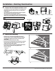
Installation - New Construction with Flex Bracket CAUTION: Make sure power is switched off at service panel before starting installation. Wear gloves during installing to help protect your hands from injury. NOTE: Ceiling mount only. IMPORTANT: Please remove the tape, which protects the damper during shipping and installation, from the duct adaptor as shown below. 1 Install the flex bracket Insert short flex bracket (C) to fan housing(A) (air outlet side), then fix short screw(F) onto it.
Installation - New Construction (continued) 3 Connecting the house and fan wires. AA Wire cover Locate the wire cover inside of the housing. Figure 1. Loosen the screw to remove the wire cover (AA) Remove the nut from the 120 V AC house wire. Use the quick connector- 3 pin (H) and quick connector -2 pin (I) to secure the 120V AC house wirings to the fan wires as shown in the wiring diagram on page 3. Figure 2.
Installation - New Construction (continued) 7 Install the grille Attach the grille by squeezing one spring together and inserting the springs into the spring guides in the fan housing (A). Connect male and female terminals from the wire cover(AA) and grille(B). Then insert the other spring and push the grille (B) up against the ceiling. Check that the installation is secure and safe from falling objects.
Installation - Existing Construction 3 Remove the duct connector and wire cover To remove the wire cover (AA), locate the screw found on the inside of the housing securing the wire cover. Remove the screw. Figure 1. To remove the fan motor, locate the two screws on opposite sides of the motor and remove them. Figure 2. To remove the duct connector(BB), pull up on the finger latch. Slide the duct connector(BB) up to remove from the fan housing (A).
Installation - Existing Construction(continued) 5 6 Connecting the house and fan wires. Remove the nut from the 120 V AC house wire. Use the quick connector- 3 pin (H) and quick connector -2 pin (I) to secure the 120V AC house wirings to the fan wires as shown in the wiring diagram on page 3. Carefully push the connected wires back into the wiring fan housing (A).
Installation - Existing Construction(continued) 9 Install the grille Attach the grille by squeezing one spring together and inserting the springs into the spring guides in the fan housing (A). Connect male and female terminals from the wire cover(AA) and grille(B). Then insert the other spring and push the grille (B) up against the ceiling. Check that the installation is secure. Turn on electricity at the breaker box after finishing the installation.
Mode Operation Two modes : Full speed and sensor mode. Toggle the light switch quickly (within 3 seconds) to switch between the modes. Sensor mode can be motion sensor or humidity sensor. NOTE: Sensor mode is the default mode when starting the fan operation. Mode Function Full Speed 80CFM or 11OCFM Motion Sensor Sensor Mode Humidity Sensor Description Indicator Select the desired airflow in a prior step with the toggle switch found on the housing.
Troubleshooting Problem Possible Cause Solution The CFM is too great. The damper is damaged or not working properly. The fan seems louder than it should. The bend in the duct is too close to the fan discharge. Be sure you do not have any sharp bends in the duct closer than 18 in. to the fan discharge. The fan discharge is reduced to fit a smaller duct Use the recommended size ducting to reduce fan noise. The fan body is not attached securely.
Questions, problems, missing parts, before returning to the store, call Hampton Customer Service 8 a.m. – 6 p.m., EST, Monday - Friday 1-855-HD-HAMPTON HOMEDEPOT.COM Retain this manual for future use. 4021V1.