
Brochure


8
Name Description
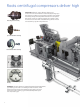
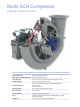
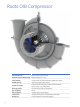
Compressor/Gear Box
Assembly incorporating a centrifugal compressor (rotor assembly, inlet hous-
ing, volute, casing cover, and bearing stand) and a speed increasing gear box
in one housing. The compressor design is capable of facilitating the use of
both inlet guide vanes as well as diffuser vanes (variable or fi xed) for optimal
effi ciency over a wide range of performance points. Capable of meeting API-
672 and API-617.
Driver
Primary drive options are electric motors, with or without variable frequency
drive, and steam turbines. In select instances internal combustion (IC) engines
have been utilized.
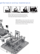
Lube Oil System
The standard IGCH design lends itself to the use of an integral lube system;
in which the lube oil reservoir is housed within the structure of the baseplate,
with the lube oil components (pumps, valves, coolers, and fi lters) mounted on
top of the reservoir with the compressor. If specifi ed, the lube system can be
a separate console shipped loose for installation near the compressor. Lube
systems can be designed to meet API-614 Chapters 2 or 3, as well as API-672.
Baseplate
Boxed construction utilizing structural supports for bracing and rigidity.
Grouting pockets, anchor bolt holes and leveling screws are incorporated
into the design to provide additional stability and rigidity during operation.
Lifting lugs are incorporated into the design for ease in transportation of the
equipment from the factory to the job site. Compressors can additionally be
supplied with a drip lip and/or non-skid decking.
Controls
Provide conditional monitoring for the compressor, driver and lube oil system.
Additionally,the local control panel (baseplate or off mounted) houses the
intelligence for positioning inlet guide vanes and variable discharge diffuser
vanes. The local instrumentation and panel provide real-time, local data
through gauges, switches, or transmitters.