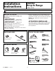
Installation Instructions Electric Drop-In Range JDS28, JDP39 Questions? Call 800.GE.CARES (800.432.2737) or Visit our Website at: ge.com • Proper installation is the responsibility of the installer and product failure due to improper installation is NOT covered under the warranty. • NOTE – This appliance must be properly grounded. BEFORE YOU BEGIN Read these instructions carefully and completely. • IMPORTANT • IMPORTANT — Save these instructions for local inspector’s use.
Installation Instructions IMPORTANT SAFETY INSTRUCTIONS FOR YOUR SAFETY ELECTRICAL REQUIREMENTS This appliance must be supplied with the proper voltage and frequency, and connected to an individual, properly grounded branch circuit, protected by a circuit breaker or fuse having amperage as noted on rating plate. (Rating Plate is located behind the oven door on the range.) WARNING: For personal safety, remove house fuse or open circuit breaker before beginning installation.
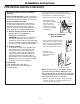
Installation Instructions PRE-INSTALLATION CHECKLIST Door removal is not a requirement for installation of the product, but is an added convenience. To remove the door: • Move Range Indoors In Front of Cabinet Opening • Protect the kitchen floor! Flatten and place a piece of the shipping carton in front of the installation location to protect the flooring. • Open the oven door as far as it will go. • Push both hinge locks down toward the door frame, to the unlocked position.
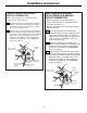
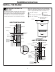
Installation Instructions PRE-INSTALLATION CUTOUT AND REQUIRED CLEARANCES NOTE: Drop-In Ranges are designed to hang from the countertop only. Do not install on a platform or support rails. If cabinets are placed less than 30” min. above the range, see alternate construction. 30” ranges conform to U.L. requirements for 0” spacing from vertical walls below countertops. Allow 1/4” minimum clearance at the back wall above the countertop.
Installation Instructions PREPARE TO INSTALL THE RANGE STANDARD INSTALLATION Wall Flat area R 1/4” min. flat 25” typically 23-3/16” 9/16” min. flat 1/4” 9/16” min. flat Range support 29-15/16”– 30-1/16” smooth cut Countertop Braces secured between the underside of the countertop and the cabinet if required to obtain 1-1/4” minimum thickness (two sides) The Standard Installation of this Drop-In Range is to hang by the countertop on the side metal flanges under cooktop.
Installation Instructions ELECTRICAL CONNECTIONS 1 Remove house fuse or open circuit breaker. 2 Loosen screws for the junction box cover and rotate out of place or remove the cover. 3 Examine the junction box location to determine the best routing of the conduit, and select the best available 7/8” diameter knockout. Avoid using holes in the top of the junction box to prevent the conduit from interfering with the back of the range.
Installation Instructions NEW CONSTRUCTION AND FOUR-CONDUCTOR BRANCH CIRCUIT CONNECTION THREE-CONDUCTOR BRANCH CIRCUIT CONNECTION When connecting to a 3-conductor branch circuit, if local codes permit: 7a Connect the bare oven ground conductor with the crimped neutral (white) lead to the branch circuit neutral (white or gray in color), using wire nuts.
Installation Instructions ELECTRICAL CONNECTIONS 8 (CONT.) Reinstall Junction box cover. Do not shorten the flexible conduit. The conduit strain relief clamp must be securely attached to the junction box and the flexible conduit must be securely attached to the clamp. If the flexible conduit will not fit within the junction box, do not install the oven until a clamp of the proper size is obtained.
Installation Instructions INSTALL THE RANGE 1 INSTALLING THE ANTI-TIP BRACKET Select the proper position for the countertop thickness and move bracket to proper position. (Unit is supplied with bracket in position 1.) The anti-tip bracket is attached to the back of the Drop-In Range. It is designed to fit under the bottom of the countertop opening at the rear. Measure counter thickness at back of cutout to determine correct bracket location. 1 For 3/4” Counter 4 For 3.5” 2 For 1.
Installation Instructions INSTALL THE RANGE (CONT.) 2 INSTALL STOP SCREW 3 PLACING THE RANGE INTO THE OPENING These screws prevent the range from sliding out of position during operation. It is suggested that two people lift the range into place, carefully setting the side metal flanges on the edges of the countertop opening. Carefully slide the range toward the back of the opening. In the last 1” of travel, lift the front of the range approx.
Installation Instructions 4 CHECK FOR PROPER INSTALLATION OF THE STOP SCREW 5 ATTACH THE LOWER TRIM Attach the lower trim (supplied separately with the range) to the bottom of the vertical side trim with the 2 screws supplied. Look at both sides of the range under the door. The stop screws must be located in the notch on the sides of the range, and not touch the top of the notch when the range is fully seated on the countertop.
Installation Instructions INSTALL THE RANGE (CONT.) REPLACING THE OVEN DOOR 9 NOTE: The oven door is heavy. You may need help lifting the door high enough to slide it into the hinge slots. Do not lift the door by the handle. 6 Hinge in locked position Lift the oven door by placing one hand on each side. The door is heavy, so you may need help. Do not lift the door by the handle.
Installation Instructions 12 FINAL CHECKLIST • Check to make sure the circuit breaker is closed (Reset) or the circuit fuses are replaced. • Be sure power is in service to the building. • Check to be sure that all packing materials and tape on metal panel (if applicable) under control knobs and drawer have been removed. 13 OPERATION CHECKLIST • Check to make sure the Clock display is energized. If a series of horizontal red lines appear in the display, disconnect power immediately.
Installation Instructions ALTERNATE CONSTRUCTION PREPARATION A OPTIONAL MAINTOP FILLER OR BACKGUARD KIT B ISLAND INSTALLATION When installing in an island or other non-standard location, countertop cutout dimensions must be according to page 5. If counter opening extends to the wall, it will require Maintop Filler Kit (JXS66XX) or Backguard Kit (JXS32XX) to close the gap. For the anti-tip bracket instructions, see page 9.
Notes 15
Notes 16 Printed in the United States