
Installation Guide

Electrical Connections
Thermal
protector
AC line
From
module
holder
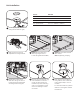
Connect the black (line) of the AC line to the black 120V, 277V,
or 347V wire. Connect the white (neutral) wires of the AC line
to the white wires using the provided 18-12 AWG push-in
connectors. Connect the green wire to the ground screw.
Optional: If using a 0-10V dimming controller, connect
matching-colored wires together.
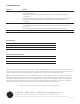
Risk of damage: Make sure that supply connection, light
xture wiring, and dimming cables are connected to proper
driver inputs. Wrong connection may cause damage to the
product.
Must use UL approved conduit ttings for all enclosure
box connections to prevent wire cuts by sharp edges and
excessive strain on wiring.
Make appropriate connections to the output wires of the
LED driver using twist-on wire connectors. Follow lighting
controller installation instructions.
NOTE: For 0-10V dimming SKUs.
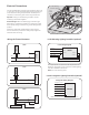
0-10V Dimming Lighting Controller (optional)Wiring the Thermal Protector
Line (black)
Neutral (white)
Ground (green)
(1-10) + (violet)
(1-10) - (gray)
DRIVER
(0-10V) -
(0-10V) +
Line
Neutral
Ground
0-10V wiring diagram
Black
120V
White Common
Blue
THERMAL
PROTECTOR
DRIVER
120V
THERMAL
PROTECTOR
277V
Black
White Common
Red
DRIVER
277V
0-10V dimming
controller (optional)
Black
Violet
White
Black
Black
Neutral
347V Input
Common
Red Line
THERMAL
PROTECTOR
DRIVER
347V
347V TRANSFORMER
Lutron Ecosystem Lighting Controller (optional)
Ecosystem Wiring Diagram
DRIVER
EcoSystem (purple)
EcoSystem (purple)
Line (black)
Neutral (white)
Ground (green)
See Note
Note: DL, for use with 3-wire uorescent control, (Lutron System)
E1
E2
L
DL
N