
Data Manual


4
Specifications subject to change.
Power connection kits are required on all Zoneline chassis. (See chart.)
The correct kit for the installation is determined by the voltage and amperage
of the electrical circuit and the means of connecting the unit to the building
wiring. If the unit is to be plugged into a receptacle, a line cord kit would be
used; if the unit is to be permanently connected, a direct connector or
a permanent connection kit would be used.
Note: 265-volt cord set units must be installed in compliance with National
Electrical Code
(440.60).
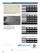
POWER CONNECTION KIT
Required on all models. See specification sheet for heater KW and branch circuit ampacity.
Receptacles/Sub-bases
Tandem
230/208V 15 Amp
NEMA6-15R
Perpendicular
230/208V 20 Amp
NEMA6-20R
Large tandem
230/208V 30 Amp
NEMA6-30R
265V 15 amp
NEMA7-15R;
receptacle used on
265V sub-base
265V 20 amp
NEMA7-20R;
receptacle used on
265V sub-base
265V 30 amp
NEMA7-30R;
receptacle used on
265V sub-base
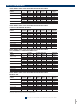
230/208-Volt, Sub-Base-Connected Units (Loads may vary by model)
Sub-base
Electric heat
BTUH
Electric heater
watts
Electric heat
amps
Recommended
circuit protection
(amps)
RAK204D15C 8,100/6,600 2,400/1,960 10.6/9.7 15
RAK204D20C 11,600/9,400 3,400/2,780 15.1/13.8 20
RAK204D30C 16,300/13,400 4,800/3,930* 21.2/19.3 30
Each line cord kit has an integral Leakage Current Detection and Interruption (LCDI) device
as required by National Electrical Code (NEC) and Underwriters Laboratories (UL) for units
manufactured after August 1, 2004.
265-Volt, Permanently Connected Units —AZ45 & AZ65 Series (Loads vary by model)
Sub-base
Power
connection kit
Electric heat
BTUH
Electric
heater watts
Electric heat
amps
Recommended
circuit protection
(amps)
RAK204E15C RAK515P 8,100 2,400 9.6 15
RAK204E20C
RAK520P 11,600 3,400 13.1 20
RAK204E30C
RAK530P 16,300 4,800* 18.4 25
265-volt units are to be permanently connected in compliance with National Electrical Code
and local codes and have a factory-installed junction box on the chassis.
Each 265-volt sub-base kit consists of sub-base with appropriate receptacle for minimum
circuit amperage, power connection kit, chaseway to route power connector from sub-base
to chassis and wiring to connect sub-base to building wiring.
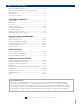
230/
208-Volt
Line-Cord-Connected (P) and
Direct-Connected Units (D)
BTUh size 7,000/9,000 12,000/15,000
Power
connection kit
RAK315P &
RAK315D
RAK320P &
RAK320D
RAK330P &
RAK330D
RAK315P &
RAK315D
RAK320P &
RAK320D
RAK330P &
RAK330D
Total wat ts 2,410/1,990 3,420/2,830 4,830/3,990* 2,430/2,020 3,450/2,860 4,860/4,020*
Heater watts 2,400/1,960 3,400/2,780 4,800/3,930* 2,400/1,960 3,400/2,780 4,800/3,930*
Heater BTUh 8,100/6,600 11,600/9,400 16,300/13,400* 8,100/6,600 11,600/9,400 16,300/13,400*
Total Am ps 10.5/9.6 14.9/13.6 21.0/19.2 10.6/9.7 15.1/13.8 21.2/19.3
MCA 15 20 25 15 20 25
Recommended
protective
device (MOCP)
15 amp
time-delay fuse
or breaker
20 amp
time-delay fuse
or breaker
30 amp
time-delay fuse
or breaker
15 amp
time-delay fuse
or breaker
20 amp
time-delay fuse
or breaker
30 amp
time-delay fuse
or breaker
265-Volt Permanent (P, Cord Set) and Direct-Connected Units (D)
BTUh size 7,000/9,000 12,000/15,000
Power
connection kit
RAK515P &
RAK515D
RAK520P &
RAK520D
RAK530P &
RAK530D
RAK515P &
RAK515D
RAK520P &
RAK520D
RAK530P &
RAK530D
Total watts 2,440 3,450 4,850* 2,460 3,470 4,870*
Heater watts 2,400 3,400 4,800* 2,400 3,400 4,800*
Heater BTUh 8,100 11,600 16,300* 8,100 11,600 16,300*
Total amps 9.1 12.9 18.1 9.3 13.1 18.4
MCA 15 20 25 15 20 25
Recommended
protective
device (MOCP)
15 amp
time-delay fuse
or breaker
20 amp
time-delay fuse
or breaker
25 amp
time-delay fuse
or breaker
15 amp
time-delay fuse
or breaker
20 amp
time-delay fuse
or breaker
25 amp
time-delay fuse
or breaker
Units connected through sub-base do not require an LCDI or AFCI device since they are not
considered to be line-cord-connected.
Each 230/208 volt sub-base kit consists of sub-base with appropriate receptacle for
minimum circuit amperage, chaseway to route power connector from sub-base to chassis,
wiring to connect sub-base to building wiring and a short line cord with 4-pin connector to
connect to chassis and plug into receptacle in sub-base. Short sub-base line cord may not be
used without sub-base.
Junction box for 230/208-volt chassis is ordered separately.
RAK4002D for AZ45 and AZ65 Series units.
*Wattage reduced with low-speed fan.
ZONELINE CHASSIS
NOMENCLATURE
The Zoneline chassis is identified by
a model number defining the type
of unit, cooling capacity, electrical
information and optional features
included on the unit. When specifying
or ordering the Zoneline chassis, the
use of this nomenclature will assure
receiving the correct unit.
230/208-volt line-cord connected units — order line cord kit.
230/208-volt sub-base connected units — order sub-base (includes power connection kit) and junction
box for chassis.
265-volt units — order sub-base and power connection kit separately.
ESSENTIAL ELEMENTS ORDERING OVERVIEW
AZ65H12DAD
Chassis series
45=cool/electric heat
65= heat pump
Zoneline
Unit type
E= cooling with electric
resistance heat
H= heat pump with electric
resistance heat backup
Nominal cooling capacity
07=7,000 BTUh cooling
09=9,000 BTUh cooling
12=12,000 BTUh cooling
15=15,000 BTUh cooling
Special features
B=base unit
C= Premium Guard
Seacoast Protection
D= Internal Condensate
Removal (ICR)
system (AZ65 only)
M=Makeup Air
P=Dry Air 25 (AZ45 only)
Voltage/Phase/Frequency
D= 230/208 Volt, single
phase, 60 Hz
E= 265 Volt, single phase,
60 Hz
A= universal power
connection
B= Digital Makeup
Air module with
universal power
connection
HEATER WATTAGE AND POWER CONNECTION KITS
ARCHITECTS & ENGINEERS DATA MANUAL AZ45/AZ65 SERIES