AIR CONDITIONER Floor type DESIGN & TECHNICAL MANUAL INDOOR AGU9RLF AGU12RLF AGU15RLF OUTDOOR AOU9RLFF AOU12RLFF AOU15RLFF
1. INDOOR UNIT FLOOR TYPE : AGU9RLF AGU12RLF AGU15RLF DTR_AG006E_03 2014.08.
1. INDOOR UNIT 1. FEATURES............................................................................................................... 01 - 01 2. WIRELESS REMOTE CONTROLLER................................................ 01 - 04 3. SPECIFICATIONS. ............................................................................................. 01 - 06 4. DIMENSIONS......................................................................................................... 01 - 07 5. WIRING DIAGRAMS..............
FLOOR TYPE AGU9-15RLF MODEL AGU9RLF / AOU9RLFF AGU12RLF / AOU12RLFF AGU15RLF / AOU15RLFF FEATURES Energy Efficiency zz Seasonal Energy Efficiency Ratio (SEER) Heating Seasonal Performance Factor (HSPF) AGU9RLF 26.0 12.6 MODEL AGU12RLF 22.7 11.6 AGU15RLF 20.3 11.
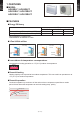
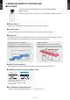
FLOOR TYPE AGU9-15RLF FLOOR TYPE AGU9-15RLF Flexible & easy installation zz Piping space is wide and connection work is easy. Beneath standard window Standard concave portion Wall Half concealed Min. 940(37) 600 (23-5/8) Min. 590 (231/4) Min. 700 (279/16) 700 (27-9/16) 740 (29-1/8) Min. 730 (28-3/4) Max. 150 (5-7/8) 200 (7-7/8) Unit: mm(in.) Unit: mm(in.) Unit: mm(in.) Space is wide and piping work is easy Choice of 6-direction drain & piping connection Back view Front view Max.
Apple-catechin filter Long-life ion deodorization filter - (01 - 03) - FLOOR TYPE AGU9-15RLF FLOOR TYPE AGU9-15RLF Air conditioner filter feature zz
FEATURES 4 mode timer setup available (ON / OFF / PROGRAM / SLEEP). Easy operation. Easy to change custom code (max. 4 custom codes) by button operation. REG1U Built-in timers zz Select from four different timer programs (On / Off / Program / Sleep). Program timer zz The program timer operates the on and off timer once within a 24-hour period.
FLOOR TYPE AGU9-15RLF FLOOR TYPE AGU9-15RLF FUNCTIONS Signal transmitter MODE button FAN button MIN. HEAT button ECONOMY button SWING button TEMP.
FLOOR TYPE Type INVERTER HEAT PUMP Model name AGU9RLF AGU12RLF Power source Available voltage range 187 - 253 V Rated Cooling Min. - Max. Capacity Rated Heating Min. - Max. Cooling Input power Heating Current AGU15RLF 208 / 230 V ~ 60 Hz Cooling Heating kW 2.64 3.52 4.16 Btu/h 9000 12000 14,200 kW 0.90 - 3.80 0.90 - 4.20 0.90 - 5.20 Btu/h 3100 - 13,000 3100 - 14,300 3100 - 17,700 kW 3.52 4.69 5.28 Btu/h 12000 16000 18000 kW 0.90 - 5.50 0.90 - 5.70 0.90 - 6.
Unit: in.
MODEL:: AGU9RLF, AGU12RLF, AGU15RLF TO OUTDOOR UNIT - (01 - 08) - FLOOR TYPE AGU9-15RLF FLOOR TYPE AGU9-15RLF 555WIRING DIAGRAMS
FLOOR TYPE AGU9-15RLF 66666COOLING CAPACITY MODEL:: AGU9RLF AFR 336 Outdoor temperature Indoor temperature °FDB 64 70 75 80 85 °FWB 54 60 63 67 71 90 73 °FDB TC SHC IP TC SHC IP TC SHC IP TC SHC IP TC SHC IP TC SHC IP 15 7.84 6.74 0.20 8.86 6.73 0.21 9.34 7.43 0.21 10.00 7.79 0.21 10.69 7.98 0.21 11.02 8.86 0.21 23 7.52 6.44 0.22 8.50 6.44 0.23 8.96 7.10 0.23 9.59 7.45 0.23 10.25 7.62 0.24 10.57 8.47 0.24 32 7.11 6.23 0.22 8.
AFR FLOOR TYPE AGU9-15RLF 336 Outdoor temperature Indoor temperature °FDB 64 70 75 80 85 °FWB 54 60 63 67 71 90 73 °FDB TC SHC IP TC SHC IP TC SHC IP TC SHC IP TC SHC IP TC SHC 15 10.08 8.23 0.30 11.39 8.22 0.30 12.01 9.06 0.31 12.86 9.51 0.31 13.74 9.73 0.31 14.17 10.81 0.32 IP 23 9.57 7.90 0.34 10.81 7.89 0.34 11.40 8.70 0.34 12.21 9.13 0.35 13.05 9.35 0.35 13.45 10.39 0.35 32 9.27 7.55 0.36 10.48 7.54 0.37 11.05 8.31 0.
AFR FLOOR TYPE AGU9-15RLF 383 Outdoor temperature Indoor temperature °FDB 64 70 75 80 85 °FWB 54 60 63 67 71 °FDB TC SHC IP TC SHC IP TC SHC IP 15 12.17 9.38 0.40 13.75 9.37 0.41 14.49 10.33 0.41 23 11.85 9.06 0.43 13.39 9.05 0.44 14.12 9.98 32 11.53 8.77 0.44 13.03 8.75 0.45 13.74 9.66 41 11.40 8.71 0.45 12.88 8.70 0.46 13.58 50 11.37 8.68 0.47 12.85 8.67 0.48 59 10.71 8.62 0.48 12.10 8.61 67 11.59 9.12 0.61 13.10 77 12.30 9.
FLOOR TYPE AGU9-15RLF This table is created using the maximum capacity. MODEL:: AGU9RLF AFR 353 Outdoor temperature Indoor temperature °FDB °FDB °FWB 60 65 TC IP TC IP TC 70 IP TC 75 IP -5 -7 12.55 1.94 12.15 2.00 11.74 2.06 11.33 2.13 5 14 23 32 41 47 50 59 3 12 19 28 37 43 47 50 14.38 14.96 15.46 15.89 18.47 20.09 22.20 23.02 2.04 2.07 2.00 1.77 1.72 1.74 1.74 1.75 13.92 14.48 14.97 15.39 17.88 19.46 21.50 22.30 2.11 2.14 2.06 1.82 1.76 1.78 1.79 1.80 13.45 14.00 14.
FLOOR TYPE AGU9-15RLF FLOOR TYPE AGU9-15RLF MODEL:: AGU15RLF AFR 383 Outdoor temperature Indoor temperature °FDB °FDB °FWB 60 65 TC IP TC IP TC 70 IP TC 75 IP -5 -7 17.12 2.77 16.58 2.85 16.02 2.94 15.46 3.03 5 14 23 32 41 47 50 59 3 12 19 28 37 43 47 50 18.95 20.07 20.92 21.34 21.93 22.23 24.55 25.46 2.87 2.79 2.59 2.20 1.96 1.90 1.97 1.98 18.35 19.44 20.26 20.67 21.24 21.53 23.78 24.65 2.95 2.87 2.67 2.26 2.01 1.95 2.02 2.03 17.73 18.78 19.57 19.97 20.52 20.80 22.97 23.
FLOOR TYPE AGU9-15RLF FLOOR TYPE AGU9-15RLF 777FAN PERFORMANCE AND CAPACITY 77777 AIR VELOCITY DISTRIBUTION MODEL:: AGU9RLF, AGU12RLF, AGU15RLF (ft.) (m) 7 2 3 1 0 0 3 1 Unit: ft./s (m/s) Top view Vertical airflow direction louver: Up Horizontal airflow direction louver: Center 2 (0.5) 3 (1) : UPPER FAN LOWER 2 1 3 2 7 (ft.) (m) 0 0 3 1 3 (1) 1 3 2 7 (ft.
FLOOR TYPE AGU9-15RLF FLOOR TYPE AGU9-15RLF 77777AIRFLOW MODEL:: AGU9RLF, AGU12RLF Cooling zz Fan speed Number of rotations [r.p.m] Airflow (UPPER/LOWER) HIGH MED LOW QUIET 1190/1000 1000/850 820/690 660/560 m³/h 570 l/s 158 CFM 336 m³/h 460 l/s 128 CFM 271 m³/h 360 l/s 100 CFM 212 m³/h 270 l/s 75 CFM 159 zHeating z Fan speed Number of rotations [r.p.
FLOOR TYPE AGU9-15RLF FLOOR TYPE AGU9-15RLF MODEL:: AGU15RLF Cooling zz Fan speed Number of rotations [r.p.m] Airflow (UPPER/LOWER) HIGH MED LOW QUIET 1330/1120 1100/930 890/750 660/560 m³/h 650 l/s 181 CFM 383 m³/h 520 l/s 144 CFM 306 m³/h 400 l/s 111 CFM 235 m³/h 270 l/s 75 CFM 159 zHeating z Fan speed Number of rotations [r.p.
FLOOR TYPE AGU9-15RLF 88888NOISE LEVEL CURVE MODEL:: AGU9RLF Heating zz 80 80 70 70 NC-65 60 NC-60 NC-55 50 NC-50 High NC-45 40 NC-40 NC-35 30 NC-30 NC-25 Quiet 20 NC-20 Octave band sound pressure level, dB: (0 dB=0.0002 μbar) Octave band sound pressure level, dB: (0 dB=0.
FLOOR TYPE AGU9-15RLF Cooling zz Heating zz 80 80 70 70 NC-65 60 NC-60 NC-55 50 High NC-50 NC-45 40 NC-40 NC-35 30 NC-30 NC-25 Quiet 20 NC-20 Octave band sound pressure level, dB: (0 dB=0.0002 μbar) Octave band sound pressure level, dB: (0 dB=0.
Microphone ● Air Flow 39-3/8in. (1m) FLOOR TYPE AGU9-15RLF FLOOR TYPE AGU9-15RLF 88888SOUND LEVEL CHECK POINT Air Flow 39-3/8in.
Model Name Power Supply AGU9RLF Voltage V 208 / 230 ~ Frequency Hz 60 A 0.7 Connection Cable AWG 14 Limited wiring length ft.
FLOOR TYPE AGU9-15RLF FLOOR TYPE AGU9-15RLF 1111 SAFETY DEVICES Model Protection form AGU9RLF Circuit protection Current fuse (PCB) Terminal protection Current (thermal) fuse Fan motor protection Terminal protection program AGU12RLF AGU15RLF 250V 3.
Connector INPUT OUTPUT CN14 Control input - REMARKS CN20 - Operation status output CN21 - Error status output See external input/output settings for details. 111111 EXTERNAL INPUT CONTROL INPUT (Operation/Stop or Forced stop) The air conditioner can be remotely operated by means of the following on-site work. "Operation/Stop" mode or "Forced stop" mode can be selected with function setting of indoor unit.
FLOOR TYPE AGU9-15RLF FLOOR TYPE AGU9-15RLF Parts (Optional) zz Parts name External connect kit Model name UTY-XWZXZ5 Wire (External input) : UTY-XWZXZ5 - (01 - 23) -
FLOOR TYPE AGU9-15RLF FLOOR TYPE AGU9-15RLF 111111 EXTERNAL OUTPUT OPERATION STATUS OUTPUT An air conditioner operation status signal can be output. Circuit diagram example zz Indoor unit control PC board Connected unit Connector DC 24 V 1 V Ex.)Relay unit 2 Ex.)Display Relay power supply *33 ft.(10 m) Signal Field supply *: Make the distance from the PC board to the connected unit within 33 ft.(10 m). Relay spec.: Max. DC 24 V, 10 mA to less than 500 mA.
FLOOR TYPE AGU9-15RLF FLOOR TYPE AGU9-15RLF ERROR STATUS OUTPUT An air conditioner error status signal can be output. Circuit diagram example zz Indoor unit control PC board Connected unit Connector DC 24 V 1 V Ex.)Relay unit 2 Ex.)Display Relay power supply *33 ft.(10 m) Signal Field supply *: Make the distance from the PC board to the connected unit within 33 ft.(10 m). Relay spec.: Max. DC 24 V, 10 mA to less than 500 mA.
111111 INDOOR UNIT (Setting by remote controller) ••The function settings of the control of the indoor unit can be changed by this procedure according to the installation conditions. Incorrect settings can cause the indoor unit to malfunction. ••After the power is turned on, perform the Function Setting according to the installation conditions using the remote controller. ••The settings may be selected between the following two: Function Number and Setting Value.
FLOOR TYPE AGU9-15RLF FLOOR TYPE AGU9-15RLF FUNCTION DETAILS Functions 1) Filter sign 2) Vertical airflow direction range control 3) Room temperature control for indoor unit sensor 4) Auto restart 5) Room temperature sensor switching 6) Remote controller custom code 7) External input control 8) Room temperature sensor switching (Aux.
Refer to Function 95, before performing this setting. Depending on the installed environment, correction of the room temperature sensor may be required. Select the appropriate control setting according to the installed environment. The temperature correction values show the difference from the Standard setting "00" (manufacturer's recommended value). *When Function 95-01(High insulation) is set, the Standard setting "00" will be the same as No correction "01" [0.0°F (0.0°C)].
FLOOR TYPE AGU9-15RLF FLOOR TYPE AGU9-15RLF 6) Remote controller custom code (Only for wireless remote controller) The indoor unit custom code can be changed. Select the appropriate custom code. Function number 44 (... Factory setting) Setting value 00 01 02 03 Setting description A B C D 7) External input control "Operation/Stop" mode or "Forced stop" mode can be selected. Function number 46 Setting value 00 01 02 (. . .
Function number 92 (For cooling) 93 (For heating) Setting value 00 01 02 03 04 05 06 07 08 09 10 11 12 13 14 15 16 17 (. . .Factory setting) Setting description No correction 0.0°F 0.0°C No correction 0.0°F 0.0°C -1°F (-0.5°C) -2°F (-1.0°C) -3°F (-1.5°C) -4°F (-2.0°C) More cooling Less heating -5°F (-2.5°C) -6°F (-3.0°C) -7°F (-3.5°C) -8°F (-4.0°C) +1°F (+0.5°C) +2°F (+1.0°C) +3°F (+1.5°C) +4°F (+2.0°C) Less cooling More heating +5°F (+2.5°C) +6°F (+3.0°C) +7°F (+3.5°C) +8°F (+4.
Use the following steps to select the custom code of the remote controller. 111 (Note that the air conditioner cannot receive a signal if the air conditioner has not been set for the matching custom code.)Press the START/STOP button until only the clock is displayed on the remote controller display. 222 Press the MODE button for at least five seconds to display the current custom code (initially set to ). 333 Press the SET TEMP. ( ) ( ) button to change the custom code between → → .
111111 CONTROLLER Exterior Monitor Mode Cool Menu Parts name Model No. Summary UTY-RVNUM Large and full-dot liquid crystal screen, wide and large keys easy to press, user-intuitive arrow key. UTY-RNNUM The room temperature can be controlled by detecting the temperature accurately with built-in thermo sensor. Simple remote controller UTY-RSNUM Compact remote controller concentrates on the basic functions such as Start/Stop, Fan Control, Temperature Setting and Operation mode.
2. OUTDOOR UNIT SINGLE TYPE : AOU9RLFF AOU12RLFF AOU15RLFF DTR_AO147E_01 2013.10.
2. OUTDOOR UNIT 1. SPECIFICATIONS. ............................................................................................. 02 - 01 2. DIMENSIONS......................................................................................................... 02 - 02 3. REFRIGERANT CIRCUIT............................................................................. 02 - 03 4. WIRING DIAGRAMS........................................................................................ 02 - 05 5.
Type Model name Power sourse Available voltage range Starting current Cooling Airflow rate Heating Fan Type × Q'ty Motor output Cooling Sound pressure level Heating Dimensions (H × W × D) Fin pitch Heat exchanger type Rows × Stages Pipe type Fin Type Type × Q'ty Compressor Motor output Type Refrigerant Charge Refrigerant oil Dimensions (H × W × D) Weight A CFM (m3/h) W dB (A) in. mm FPI W lbs.oz. kg Type Material Enclosure Color in. mm in. mm Net Gross Net Gross Size lbs.
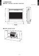
222DIMENSIONS Unit: in. (mm) OUTDOOR UNIT AOU9-15RLFF OUTDOOR UNIT AOU9-15RLFF MODEL:: AOU9RLFF, AOU12RLFF, AOU15RLFF Top view 31-1/8 (790) 2-9/16 (65) 11/16 (18) 11-7/16 (290) 7/8 (23) 3/8 (9) 13/16 (20) 24-7/16 (620) 13/16 (20) 13-7/8 (352) Front view Side view 21-1/4 (540) 6-7/8 (175) 4-5/16 (110) 12-5/8 (320) Airflow 8-1/4 (209) Drain pipe mounting place Ø13/16 (20) 4-Ø7/16 (11.3) hole Bottom view INSTALLATION PLACE When there are obstacles at the back, side(s), and top.
333REFRIGERANT CIRCUIT Heat exchanger ( INDOOR ) OUTDOOR UNIT AOU9-15RLFF 3-Way valve ThD Compressor Muffler ThR Muffler ThP 2-Way valve 4-Way valve Strainer Acccumlator Expansion valve Heat exchanger ( OUTDOOR ) Strainer ThHO ThO Cooling Heating ThD : Thermistor (Discharge Temp.) ThO : Thermistor (Outdoor Temp.) ThHO : Thermistor (Heat Exchanger Out Temp.) ThR : Thermistor (Room Temp.) ThP : Thermistor (Pipe Temp.) Refrigerant pipe diameter Liquid: 1/4" (6.35 mm) Gas: 3/8" (9.
Heat exchanger ( INDOOR ) OUTDOOR UNIT AOU9-15RLFF 3-Way valve ThD Compressor Muffler ThR Muffler ThP 2-Way valve 4-Way valve Strainer Expansion valve Heat exchanger ( OUTDOOR ) Strainer ThHO ThO Cooling Heating ThD : Thermistor (Discharge Temp.) ThO : Thermistor (Outdoor Temp.) ThHO : Thermistor (Heat Exchanger Out Temp.) ThR : Thermistor (Room Temp.) ThP : Thermistor (Pipe Temp.) Refrigerant pipe diameter Liquid: 1/4" (6.35 mm) Gas: 1/2" (12.
444WIRING DIAGRAMS OUTDOOR UNIT AOU9-15RLFF OUTDOOR UNIT AOU9-15RLFF MODEL:: AOU9RLFF, AOU12RLFF - (02 - 05) -
OUTDOOR UNIT AOU9-15RLFF OUTDOOR UNIT AOU9-15RLFF MODEL:: AOU15RLFF - (02 - 06) -
555CAPACITY COMPENSATION RATE FOR PIPE LENGTH AND HEIGHT DIFFERENCE OUTDOOR UNIT AOU9-15RLFF Pipe length (m) COOLING Û1 Indoor unit is higher than outdoor unit. Height difference H Û2 Indoor unit is lower than outdoor unit 5m 7.5m 10m 15m 20m 17ft. 25ft. 33ft. 50ft. 67ft. 15m 50ft. - - - 0.893 0.909 10m 33ft. - - 0.955 0.908 0.924 7.5m 25ft. - 0.975 0.959 0.912 0.928 5m 17ft. 0.992 0.979 0.963 0.916 0.931 0m 0ft. 1.000 0.987 0.970 0.923 0.939 -5m -17ft. 1.
OUTDOOR UNIT AOU9-15RLFF Pipe length (m) COOLING Û1 Indoor unit is higher than outdoor unit. Height difference H Û2 Indoor unit is lower than outdoor unit 5m 7.5m 10m 15m 20m 17ft. 25ft. 33ft. 50ft. 67ft. 15m 50ft. - - - 0.951 0.950 10m 33ft. - - 0.979 0.967 0.966 7.5m 25ft. - 0.988 0.983 0.971 0.970 5m 17ft. 0.994 0.992 0.987 0.975 0.974 0m 0ft. 1.002 1.000 0.995 0.983 0.982 -5m -17ft. 1.002 1.000 0.995 0.983 0.982 -7.5m -25ft. - 1.000 0.995 0.
666ADDITIONAL CHARGE CALCULATION MODEL:: AOU9RLFF, AOU12RLFF Refrigerant amount R410A lbs. oz. 2lbs.10oz. g 1200 Refrigerant charge zz Pipe length Additional charge ft. 49 or less 66 (MAX) m 15 or less oz. 0 20 (MAX) 0.22oz./ft. (20g/m) +3.5 g 0 +100 MODEL:: AOU15RLFF Refrigerant type Refrigerant amount R410A lbs. oz. 2lbs.12oz. g 1250 Refrigerant charge zz Pipe length Additional charge ft. 49 or less 66 (MAX) m 15 or less oz. 0 20 (MAX) 0.22oz./ft. (20g/m) +3.
777AIRFLOW MODEL:: AOU9RLFF Number of rotations (r.p.m.) 870 Airflow m3/h 2050 l/s 569 CFM 1207 Heating zz Number of rotations (r.p.m.) 870 Airflow m3/h 2050 l/s 569 CFM 1207 MODEL:: AOU12RLFF Cooling zz Number of rotations (r.p.m.) 1050 Airflow m3/h 2475 l/s 688 CFM 1457 Heating zz Number of rotations (r.p.m.
MODEL:: AOU15RLFF Number of rotations (r.p.m.) 1050 Airflow m3/h 2475 l/s 688 CFM 1457 Heating zz Number of rotations (r.p.m.
888OPERATION NOISE 88888NOISE LEVEL CURVE Heating zz 80 80 70 70 NC-65 60 NC-60 NC-55 50 NC-50 NC-45 40 NC-40 NC-35 30 NC-30 NC-25 20 NC-20 Octave band sound pressure level, dB: (0 dB=0.0002 µbar) Octave band sound pressure level, dB: (0 dB=0.
Heating zz 80 80 70 70 NC-65 60 NC-60 NC-55 50 NC-50 NC-45 40 NC-40 NC-35 30 NC-30 NC-25 20 NC-20 Octave band sound pressure level, dB: (0 dB=0.0002 µbar) Octave band sound pressure level, dB: (0 dB=0.
OUTDOOR UNIT AOU9-15RLFF OUTDOOR UNIT AOU9-15RLFF 88888SOUND LEVEL CHECK POINT 39-3/8in.
999ELECTRIC CHARACTERISTICS OUTDOOR UNIT AOU9-15RLFF Power supply MCA Starting Current *1) Wiring Spec.: Voltage Frequency MAX. CKT. BKR Power Cable V Hz A A A AWG AOU9RLFF 4.1 10.8 15 14 AOU12RLFF 208 / 230 ~ 60 6.7 *1) Wiring Spec.: Selected Sample (Selected based on Japan Electrotechnical Standard and Codes Committee E0005) MCA: Min Circuit Amp(Calculation based on UL1995) MAX. CKT. BKR: Maximum Circuit Breaker - (02 - 15) - AOU15RLFF 13.8 7.
1111 SAFETY DEVICES OUTDOOR UNIT AOU9-15RLFF AOU9RLFF AOU12RLFF AOU15RLFF 250V 20A Current fuse (Near the terminal) 250V 25A 250V 5A Circuit protection Current fuse (Main printed circuit board) 250V 15A 250V 10A 250V 3.15A 250V 3.15A Fan motor protection Thermal protection program OFF: 212 ± 27 °F (100 ± 15 °C) ON: 203 ± 18 °F (95 ± 10 °C) Compressor protection Thermal protection program (Discharge temp.