
User's Manual
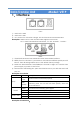


Table Of Contents

- 2 -
Data Transfer Unit
Model: V519
1
.
Interface
Front
1) RJ45 Jack: LAN0
2) RJ45 Jack: LAN1
3) DC Jack: DC7V~35V wide voltage, DC12V is better and recommended.
Description: LAN0 can be used as WAN under regular router mode;
DC: 2.1mm Standard Round Interface, 7V~35V, Internal:+, Outside: -
Back
1) 3G/4G/WIFI Antenna: SMA external rotation internal hole interface.
2) RESET: press for >5s when it’s powered on, SYS indicator will flash quickly and it’ll
reboot. Then all settings will be reset to the default factory settings.
3) Serial Port: 4PIN PH2.0mm, GND/TX/RX/DC+ from left to right, DC+ can be used
power supply to power on the router.
4) SIM card slot: Self-locking slot, press the white button on your left side and it will
pop out.
Description for Indicator
Name Status Description
(SYS)
Indicat
or On
Powered and connected properly
Flash
Quickly
Abnormal connection; 3G/4G dialing; system reset
indicator, press for >5s and it’ll flash quickly, then the
router will reboot.
3G/4G
Green Connected successfully, good signal
Red Connected successfully, bad signal
Off Failed to connect to 3G/4G module or abnormal
LAN0、LAN1
On RJ45 is connected
Off RJ45 is out of connection
Description for Serial Port
: