
Installation Guide

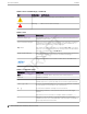

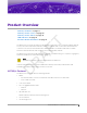

Table Of Contents
- Table of Contents
- Preface
- Product Overview
- Install the Access Point
- AP310i/e Box Contents
- Access Point Installation Options and Accessory Information
- Install the Access Point on Drywall or Wood Wall, or to a Solid Flat Ceiling
- Install the Access Point on a Suspended Ceiling or a Drop Ceiling with a Flat T-bar
- Install the Access Point on a Junction Box or Gang Box
- Install the Access Point on a Beam
- Antenna Configuration for External Antenna Model Access Point
- Access Points Specifications
- Regulatory Information
- Safety Guidelines
- MPE Statement for Mobile Devices
- Federal Communications Commission (FCC) Notice
- Industry Canada Notice
- Detachable Antenna Usage
- Australia Notice
- Brazil Anatel Statement
- Hazardous Substances
- Supplement to Product Instructions
- NCC Statement
- CE Information
- European Waste Electrical and Electronic Equipment (WEEE) Notice
- Declaration of Conformity in Languages of the European Community
- Index

Product Overview
AP310i/e Features on page 9
AP310i/e Power Source on page 10
AP310i/e Power Tables on page 10
LED Indicators on page 11
Purchase Order Information on page 11
The AP310i/e access points are indoor model 802.11ax access points. The “i” in AP310i indicates that the
access point comes with internal antennas, and the “e” indicates that it comes with external antenna
connectors. The access points feature built-in dual-band radios, two band-locked radios, four WiFi
internal or external antennas, and one Bluetooth Low Energy (BLE) antenna.
The AP310i/e is mounted on a flat surface such as a wall, a solid flat ceiling, or to a junction or gang box,
and can be installed on a suspended or drop ceiling.
Note
The AP310i/e requires a minimum base firmware of WiNG 7.3.1.
In this document, the access points are addressed as AP310i/e when the product features and
installation procedures are the same for both access points.
AP310i/e Features
The AP310i/e access points have the following features:
• Radios:
◦ Two 802.11ax radios (one 2×2 2.4 GHz and 5 GHz radio, and one 2×2 5 GHz radio)
◦ One IoT radio (2.4 GHz)
• Console port: RJ45
• Two, one gigabyte Ethernet ports
◦ GE1 port
◦ GE2 port
• LED indicators: Six
All LED indicators will be powered on during reset.
• One reset button
• One Kensington lock
ExtremeWireless™ AP310i/e Access Points 9
DRAFT