ExtremeWireless™ AP310i/e Access Points D R AF T Installation Guide 9036535-00 March 2020
Copyright © 2020 Extreme Networks, Inc. All rights reserved. Legal Notice Extreme Networks, Inc. reserves the right to make changes in specifications and other information contained in this document and its website without prior notice. The reader should in all cases consult representatives of Extreme Networks to determine whether any such changes have been made. The hardware, firmware, software or any specifications described or referred to in this document are subject to change without notice.
Table of Contents Preface...................................................................................................................................5 Text Conventions.......................................................................................................................................................... 5 Documentation and Training.................................................................................................................................. 7 Getting Help..........
Table of Contents Detachable Antenna Usage.................................................................................................................................. 37 Detachable Antenna Usage......................................................................................................................... 37 Australia Notice..........................................................................................................................................................
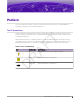
Preface This section describes the text conventions used in this document, where you can find additional information, and how you can provide feedback to us. Text Conventions T Unless otherwise noted, information in this document applies to all supported environments for the products in question. Exceptions, like command keywords associated with a specific software version, are identified in the text.
Text Conventions Preface Table 1: Notes and warnings (continued) Icon Notice type Alerts you to... Caution Risk of personal injury, system damage, or loss of data. Warning Risk of severe personal injury. Table 2: Text Description screen displays This typeface indicates command syntax, or represents information as it appears on the screen. The words enter and type When you see the word enter in this guide, you must type something, and then press the Return or Enter key.
Preface Documentation and Training Documentation and Training Find Extreme Networks product information at the following locations: Current Product Documentation Release Notes Hardware/software compatibility matrices for Campus and Edge products Supported transceivers and cables for Data Center products Other resources, like white papers, data sheets, and case studies Extreme Networks offers product training courses, both online and in person, as well as specialized certifications. For details, visit www.
Providing Feedback Preface 3. Select the products for which you would like to receive notifications. Note You can modify your product selections or unsubscribe at any time. 4. Select Submit. Providing Feedback The Information Development team at Extreme Networks has made every effort to ensure the accuracy and completeness of this document. We are always striving to improve our documentation and help you work better, so we want to hear from you.
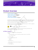
Product Overview T AP310i/e Features on page 9 AP310i/e Power Source on page 10 AP310i/e Power Tables on page 10 LED Indicators on page 11 Purchase Order Information on page 11 AF The AP310i/e access points are indoor model 802.11ax access points. The “i” in AP310i indicates that the access point comes with internal antennas, and the “e” indicates that it comes with external antenna connectors.
AP310i/e Power Source • • • • Product Overview One safety hanger provision One USB 2.0 type A connector Power: PoE at 802.3at and 802.
Product Overview LED Indicators Table 5: AP310e power table AP310e 802.3af 802.3at and DC Radio 0 (sensor) 2.4G – 2×2 (19dBm) 5G – 2×2 (17dBm) 2.4G – 2×2 (19dBm) 5G – 2×2 (17dBm) Radio 0 (2.4G) 2×2 (19dBm) 2×2 (19dBm) Radio 0 (5G–L) 2×2 (16dBm) 2×2 (16dBm) Radio 1 (5G–F) 2×2 (18dBm) 2×2 (18dBm) Radio 1 (5G–H) 2×2 (16dBm) 2×2 (16dBm) BLE On On USB Off On PSE Off On T LED Indicators The LED indicators are located on the front face of the access point but are not visibly marked.
Purchase Order Information Product Overview Table 7: Bracket purchase order information (continued) Part number Description 30516 WS-MBI-WALL04 bracket 37211 WS-MBI-DCFLUSH bracket Table 8: Bracket accessory purchase order information Description KT-135628-01 Universal mounting kit for wireless LAN (WLAN) access points 37210 Flat metal easy-attach adapter for main mounting bracket BRKT-000147A-01 Beam clip accessory 30525; WS-CAB-RJ45-FLT01 RJ45 flat cable accessory for ceiling mount bracket
Install the Access Point T AP310i/e Box Contents on page 13 Access Point Installation Options and Accessory Information on page 14 Install the Access Point on Drywall or Wood Wall, or to a Solid Flat Ceiling on page 15 Install the Access Point on a Suspended Ceiling or a Drop Ceiling with a Flat Tbar on page 21 Install the Access Point on a Junction Box or Gang Box on page 28 Install the Access Point on a Beam on page 28 AF About This Task The access point is installed on flat surfaces such as drywall
Access Point Installation Options and Accessory Information • • Install the Access Point Two Phillips pan head wood screws Two screw-in anchors Note All optional brackets and accessories are sold separately. Access Point Installation Options and Accessory Information The access point comes with the main mounting bracket (#37201; mounting bracket for 802.11ax indoor access points). There are various optional brackets, bracket adapters, and accessories that can be purchased separately.
Install the Access Point on Drywall or Wood Wall, or to a Solid Flat Ceiling Install the Access Point Table 10: Bracket and accessory usage for various installation options (continued) Mounting bracket or accessory Wall Solid Ceilin instal flat g l ceilin install g (Tinstal bar) l Ceiling install (protruded T-bar) Junctio Beam n box install install Ceiling T-bar tile widths protrusio n Notes Wall mount, ceiling mount, or install on any solid surface.
Install the Access Point Using the Main Mounting Bracket • • Install the Access Point #37201, stainless-steel main mounting bracket with #37210, flat metal easy-attach adapter Phillips pan head screws Tip The best practice is to install the access point using the mounting brackets. Install the Access Point Using the Main Mounting Bracket About This Task The main mounting bracket is a stainless-steel bracket that ships with the access point.
Install the Access Point Using the Main Mounting Bracket R AF T Install the Access Point D Figure 1: Main mounting bracket Callout Description 1 Main mounting bracket mounting holes 2 Main mounting bracket feet 2. Insert the Phillips pan head screws into the main mounting bracket holes and attach the bracket to the wall. Use screw-in anchors, if needed. 3. Connect the Ethernet cable RJ45 connector into the GE1 port. 4.
Install the Access Point Using the Main Mounting Bracket Install the Access Point Follow this procedure to install the security torx locking screw using one of the security lock holes on the access point. Note Perform this task after the access point is attached to the main mounting bracket on a drywall or wood wall. Procedure D R AF T 1. Line up the security torx locking screw using the rear guides on the access point. 2. Using a T8 bit screwdriver, tighten the security torx locking screw. 3.
Install the Access Point Install the Access Point Using the WALL04 Bracket Install the Access Point Using the WALL04 Bracket About This Task The optional WALL04 (#30516) bracket is used for wall installations, and ships with two Phillips pan head screws and two screw-in anchors. You must purchase the bracket separately. Note The locking tab on the WS-MBI-WALL04 bracket must be on the top side during installation. Procedure 1. Using the WALL04 bracket as a template, mark and drill two holes on a wall.
Install the Access Point Using the Main Mounting Bracket and Easy-Attach Adapter Install the Access Point Procedure D R AF T 1. Keep the adapter to the center of the main mounting bracket, push and rotate it. Figure 3: Flat metal easy-attach adapter being attached to the main mounting bracket 2. Using the attachment holes on the easy-attach adapter, mark and drill two hole centers on a wall or a solid flat ceiling. 3. Attach the easy-attach adapter to the wall using two Phillips pan-head screws.
Install the Access Point Install the Access Point Directly on a Wall 5. Place the access point onto the bracket feet and slide it down to lock it in place. Note The bracket feet must be pointing up. Install the Access Point Directly on a Wall About This Task If you do not want to use the main mounting bracket that ships with the access point, you can install the access point directly on a wall using two Phillips pan head screws.
Install the Access Point on a Flat T-bar Using Main Mounting Bracket Install the Access Point Install the Access Point on a Flat T-bar Using Main Mounting Bracket Before You Begin Ensure that the T-bar meets the following conditions before installing the main mounting bracket on a flat T-bar: • • • • • T-bar width must be 15/16 in. (24 mm). T-bar bottom must be flat, all the way across the ceiling. T-bar must be structurally sound. T-bar maximum base thickness must not exceed 0.055 in. (1.4 mm).
Install the Access Point on a Flat T-bar Using Main Mounting Bracket Install the Access Point D R AF T 2. Push and rotate the main mounting bracket on the T-bar in such a way that the center angled locking tabs of the main bracket gets attached to the T-bar. Figure 4: Install the main mounting bracket on a T-bar 3. Place the access point on the bracket feet and slide it down to lock it in place. Hold the access point and rock it back and forth to ensure that it is securely mounted. 4.
Install the Access Point on a Flat T-bar Using Main Mounting Bracket and KT-135628-01 Adapter Install the Access Point Install the Access Point on a Flat T-bar Using Main Mounting Bracket and KT-135628-01 Adapter Before You Begin Ensure that the T-bar meets the following conditions before installing the main mounting bracket with the KT-135628-01 adapter on a T-bar: • • • • T-bar width can be either 9/16 in. (15 mm) or 15/16 in. (24 mm). T-bar bottom must be flat all the way across.
Install the Access Point on a Flat T-bar Using the DCFLUSH bracket AF T Install the Access Point Figure 5: Attach the KT-135628-01 adapter on the main mounting bracket Callout B C KT-135628-01 adapter R A Description KT-135628-01 T-bar holder KT-135628-01 adapter locking pin D 3. Slide the KT-135628-01 T-bar holder onto the T-bar and replace the tiles to hold the adapter onto the T-bar. 4. Hold and rock the access point back and forth to ensure that it is securely mounted. 5.
Install the Access Point on a Flat T-bar Using the DCFLUSH bracket Install the Access Point About This Task The WS-MBI-DCFLUSH (#37211) bracket is used on a flat T-bar when you do not want to use the main mounting bracket on it. Procedure AF T 1. Remove the ceiling panels around the T-bar. 2. Open the movable sliding part of the DCFLUSH bracket to give the stationary and slider T-bar more space.
Install the Access Point on a Flat T-bar Using the DCMTR01 Bracket Install the Access Point Install the Access Point on a Flat T-bar Using the DCMTR01 Bracket Before You Begin Ensure that the T-bar meets the following conditions before installing the DCMTR01 bracket on it: • • • • • T-bar width must be 9/16 in. (15 mm), 15/16 in. (24 mm), or 1.5 in. (38 mm). T-bar must be structurally sound. T-bar maximum base thickness cannot exceed 0.118 in. (3 mm). T-bar maximum protrusion must be 0.625 in. (15.
Install the Access Point on a Junction Box or Gang Box 5. 6. 7. 8. 9. Install the Access Point Squeeze the bracket parts together until you hear the T-bar locking tab click into place. Slide the bracket base into the rear groove of the access point. Hold and rock the access point back and forth to ensure that it is securely mounted. Attach the RJ45 connector to the GE1 port. Replace the ceiling tile.
Install the Access Point Install the Access Point on a Beam About This Task AF T If you do not want to install the access point on a solid flat surface, you can attach it to a beam using the beam clip accessory (BRKT-000147A-01). The access point can be attached to a beam only if the beam is flat, and can support the access point in all environmental conditions.
Install the Access Point on a Beam Install the Access Point Procedure 1. Attach the beam clip to the main mounting bracket. AF T Slide the beam clip accessory into the rear hinges on either side of the main mounting bracket and slightly twist it until the clip locks into place. Figure 9: Beam clip accessory attached to the main mounting bracket R 2. Place the access point onto the main mounting bracket feet and slide it down to lock it in place. 3. Place the beam clip accessory on a beam.
Install the Access Point Install the Access Point on a Beam AF T 4. Tighten the beam clip accessory screw to secure the access point in place. Figure 10: Beam clip accessory attached to a beam D R 5. Connect the Ethernet cable RJ45 into the GE1 port.
D R AF T Antenna Configuration for External Antenna Model Access Point Figure 11: AP310e external antennas 32 ExtremeWireless™ AP310i/e Access Points
Antenna Configuration for External Antenna Model Access Point Antenna socket radio mapping information Antenna socket radio mapping information Radio 1 (R1) - antennas 1 and 2 Radio 2 (R2) - antennas 3 and 4 IoT radio - BLE antenna D R AF T • • • ExtremeWireless™ AP310i/e Access Points 33
Access Points Specifications Physical specifications Specification Dimensions 6.4 in. × 6.4 in. × 1.7 in. (165 mm × 165 mm × 45 mm) Weight 1.5 lbs. (0.70 kg) T Item Housing Plastic Six Radios AF LED Two 802.
Regulatory Information R AF T Safety Guidelines on page 35 MPE Statement for Mobile Devices on page 35 Federal Communications Commission (FCC) Notice on page 36 Industry Canada Notice on page 36 Detachable Antenna Usage on page 37 Australia Notice on page 38 Brazil Anatel Statement on page 38 Hazardous Substances on page 38 Supplement to Product Instructions on page 39 NCC Statement on page 39 CE Information on page 39 European Waste Electrical and Electronic Equipment (WEEE) Notice on page 40 Declarati
Federal Communications Commission (FCC) Notice Regulatory Information Federal Communications Commission (FCC) Notice This equipment has been tested and found to comply with the limits for a Class B digital device, pursuant to Part 15 of the FCC Rules. These limits are designed to provide reasonable protection against harmful interference in a residential installation.
Regulatory Information Detachable Antenna Usage Warning IC Radiation Exposure Statement: This equipment complies with ISED radiation exposure limits set forth for an uncontrolled environment. This equipment should be installed and operated with minimum distance of 28 cm between the radiator and your body. Warning Déclaration d'exposition aux radiations: Cet équipement est conforme aux limites d'exposition aux rayonnements ISED établies pour un environnement non contrôlé.
Australia Notice Regulatory Information Group Brand Model number Antenna type Antenna gain (dBi) 2.4 GHz 5 GHz BLE or thread Extreme AI-DQ04360S Omni 5.5 6 - 10 Extreme ML-2452SEC6M4-036 / WS-AIDQ05120 Panel 6.92 7.23 - 11 Extreme WS-AIDE07025 Panel 7.5 6.5 - 12 Extreme ML-2452PNA7-01R Panel 1 7.8 10.7 7.8 13 Extreme WS-AIDE10055 Panel 2 10.5 7.
Regulatory Information Supplement to Product Instructions D R NCC Statement AF T Supplement to Product Instructions CE Information Warning CE co-location MPE Statement: This equipment complies with CE radiation exposure limits set forth for an uncontrolled environment. This equipment should be installed and operated with minimum distance of 20 cm between the radiator and your body. The device is restricted to indoor use only when operating in the 5150 to 5350 MHz frequency range.
Selling Countries: Regulatory Information Selling Countries: AT BE BG HR CY CZ DK EE FI FR DE EL HU IE IT LV LT LU MT NL PL PT RO SK SI ES SE UK All Operational Modes 2.4GHz: 802.11b, 802.11g, 802.11n (HT20), 802.11n (HT40), 802.11ax (HEW20), 802.11ax (HEW40), 802.15.4 (Thread), Bluetooth (LE) 5GHz: 802.11a, 802.11n (HT20), 802.11n (HT40), 802.11ac (VHT20), 802.11ac (VHT40), 802.11ac (VHT80), 802.11ac (VHT160), 802.11ax (HEW20), 802.11ax (HEW40), 802.11ax (HEW80), 802.
Declaration of Conformity in Languages of the European Community Regulatory Information For information about the available collection system, please contact Extreme Environmental Compliance at Green@extremenetworks.com. Declaration of Conformity in Languages of the European Community Hereby, Extreme Networks, declares that the radio equipment type (AP310i/e) is in compliance with Directive 2014/53/EU.
Declaration of Conformity in Languages of the European Community Regulatory Information Hiermit erklärt Extreme Networks die Übereinstimmung des "WLAN Wireless Controller bzw. Access Points" (AP310i/e) mit den grundlegenden Anforderungen und den anderen relevanten Festlegungen der Richtlinie 2014/53/EU. Für den vollständigen Wortlaut der EU-Konformitätserklärung wenden Sie sich bitte an extreme Regulatory Compliance unter compliancerequest@extremenetworks.
Declaration of Conformity in Languages of the European Community Regulatory Information Extreme Networks declara que este Radio LAN device (AP310i/e) está conforme com os requisitos essenciais e outras disposições da Directiva 2014/53/EU. Para o texto integral da declaração de conformidade da UE, contacte a conformidade regulamentar extrema em compliancerequest@extremenetworks.
Index A features (continued) Kensington lock 9 LED information 9 power source 9 radios 9 reset button 9 safety hanger 9 temperature 9 USB 9 feedback 8 flat t-bar install DCFLUSH bracket 21 DCMTR01 bracket 21 KT-135628-01 adapter 21 main mounting bracket 21 T access points specifications environmental specifications 34 physical specifications 34 power specifications 34 antenna configuration 32, 33 antennas external antennas 9 internal antennas 9 Australia notice 38 beam install beam clip accessory 28 BRK
Index main bracket install (continued) wood wall install 16 main mounting bracket on flat T-bar 22 N notices 5 AF power source external 12V DC power supply 10 Power over Ethernet (PoE) 10 power tables AP310e power table 10 AP310i power table 10 product overview AP310e access point 9 AP310i access point 9 purchase order information bracket accessories beam clip accessory 11 flat metal easy-attach adapter 11 KT-135628-01 11 RJ45 flat cable accessory 11 mounting brackets main mounting bracket 11 WS-MBI-DCF