
User manual


TB-7Z-020-EMC Hardware User Manual
10
Rev.1.03
4. Block Diagram
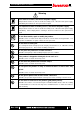
The TB-7Z-020-EMC board block diagram is shown in Figure 4-1.
PS block is connecting specific memories or interfaces.
PL block is connecting FMC connector and debug interfaces.
For more detail, please refer to each peripheral section
.
XC7Z020-1CLG484
PS
Bank502
MIO 1
Bank501
PL
Bank33, 34
DDR3
DDR3
USB
PHY
microSD
Card
Ether
PHY
Mictor
JTAG
FMC LPC
PMOD SW
LA
68
CLK
4
Address
Data 16bit
Data 16bit
MIO 0
Bank500
QSPI
128Mb
UART
CAN x1
I2C x1
PL
Bank13
PL
Bank35
LED DVI
FMC LPC
TRACEPKT
Figure 4-1 Block Diagram