Installation Guide Guide d’installation
About This Installation Guide This guide describes how to mount the ultra-short-throw projectors listed below to a wall using the included Epson® wall mount. It also explains how to install the Control Pad and Touch Unit after wall mount installation.
Handle the power cord carefully. Incorrect handling may cause fire or electric shock. Observe the following precautions when handling: • Do not handle the power plug with wet hands. • Do not use a power cord that is damaged or modified. • Do not pull the power cord with too much force when routing the cable through the wall mount. Do not install the wall mount in a place where it might be subjected to vibration or shock. Vibration or shock could cause damage to the projector or mounting surface.
Warning Do not use the Touch Unit if you are using or near medical equipment such as a pacemaker. The magnet within the Touch Unit generates electromagnetic interference which could cause medical equipment to malfunction. Caution Do not install the wall mount in a location where the operating temperature for your projector model may be exceeded. Such an environment may damage the projector.
Before installing the Touch Unit, verify that the installation location meets the following conditions: • • The Touch Unit can be secured to the surface with magnets or screws. The surface is flat, smooth, and unwarped with no more than 0.2 inches (5 mm) of unevenness in any direction on the screen surface. 0.2 in. (5 mm) • When installing on a whiteboard, install the Touch Unit within the frame of the whiteboard.
1 Package Contents s8 2 Specifications s 10 3 Connecting Devices s 14 4 Positioning the Projector s 16 1. Installation worksheet for projecting on a pre-installed wall-mounted board 2. Installation worksheet for projecting on a plain wall 3. Diagonal image size and mounting position 4. Distance from projection surface to wall plate 5. Installation measurement tables 6. Installation Measurements in Inches for WXGA Projectors 7. Installation Measurements in Inches for XGA Projectors 8.
6 Adjusting the Image s 41 English 1. Turn on the projector 2. Display the test pattern 3. Change the aspect ratio if necessary 4. Adjust the focus 5. Use the adjustment knob on the left side to adjust the horizontal roll 6. Use the adjustment knob on the right side to adjust the horizontal rotation 7. Use the adjustment knob on the top to adjust the vertical tilt 8. Adjust the horizontal slide 9. Adjust the forward/backward slide 10. Adjust the vertical slide 11.
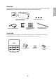
1 Package Contents Wall Mount Wall mount Wall plate cover Wall plate Hexagonal shaft 3-axis adjustment unit and slide plate (attached when shipped) Wall plate cover extender Template sheet (for installing the wall plate) VGA computer cable (may be included with projector or wall mount) Shape Open-ended wrench 13 mm (for M8 and M6) × 6 mm (for hexagonal shaft) Name Hexagon wrench (for M4) Quantity M4 × 12 mm hexagon socket head cap bolt with washer/spring washer End cap Application 6 For wall p
The following parts are packaged with your projector and are necessary when attaching the Touch Unit. When installing the Touch Unit on a non-magnetic surface, you will also need three M4 screws. Touch Unit and markers (markers are inside the unit) Label (×4) Touch Unit connection cable Spacer for screw hole (×3) Tape (approx. 2.4 inches [6 cm]) for securing the markers (×12) Infrared deflector (approx. 11.2 inches [28.
2 Specifications Item Specification Additional information Wall mount weight (including the Approx. 18.5 lb 3-axis adjustment unit, slide plate, (8.4 kg) wall plate, wall plate cover, wall plate cover extender, and end cap) Reference Page — Wall mount: 6.6 lb (3.0 kg) 3-axis adjustment unit: 2.6 lb (1.2 kg) Slide plate: 1.8 lb (0.8 kg) Wall plate: 6.0 lb (2.7 kg) Wall plate cover and end cap: 0.9 lb (0.4 kg) Wall plate cover extender: 0.6 lb (0.3 kg) Maximum load capacity 15.
English Horizontal slide adjustment range 1.8 in. (45 mm) 1.8 in. (45 mm) Forward/backward slide adjustment range Arm slide adjustment range 10.7 in. (273 mm) Adjustment from 3-axis adjustment unit installation position By changing the installation position of the 3-axis adjustment unit to the front or back, you can adjust the installation position of the projector. When the screen size is less than 75 inches, install it at the position marked with a stamp on the mount arm.
Touch Unit External dimensions and weight 3.7 in. (95 mm) The Touch Unit weighs approximately 16 ounces (450 g). 8.3 in. (210 mm) 2.0 in. (51 mm) Attached labels The Touch Unit is a Class 1 laser product that conforms to the JIS C 6802:2011 standard. There are warning labels affixed to the Touch Unit to indicate that it is a Class 1 laser product.
External dimensions and weight The Control Pad weighs approximately 8.5 ounces (240 g). 4.4 in (111 mm) 5.4 in (135.9 mm) 4.3 in (109 mm) 4.0 in (104 mm) 0.1 in (3.5 mm) 0,6 in (15.47 mm) 4.2 in (107 mm) 6.0 in (153.5 mm) 1.1 in (29 mm) 1.2 in (30.9 mm) 5.9 in (149 mm) 0.4 in (11.5 mm) Cable routing holes When routing cables through a wall, use the position ( ) in the following figure as the cable routing hole. Otherwise, remove the cable cover ( ) and route the cables through the opening.
3 Connecting Devices Make sure you have the power cord, computer cable, and other parts at the location where the wall mount is to be installed. Make sure you also have all necessary cables for the Touch Unit and other devices, such as a document camera or microphone, that you will connect to the projector. Your projector’s connection panel may differ slightly from the displayed model. For details, refer to the online User’s Guide for your projector.
The Control Pad is included with the BrightLink Pro 1410Wi/1420Wi/1430Wi projectors. It provides a convenient alternative to the remote control for turning on the projector, changing the source, and selecting whiteboard mode. You can also use the control pad to capture, print, and save your projected images. You must install the control pad on the same surface as the projector, within the range specified in the installation instructions.
4 Positioning the Projector BrightLink Pro 1410Wi/1420Wi/1430Wi, BrightLink 475W/485W, BrightLink 575Wi/585Wi/595Wi, BrightLink 575Wi+/585Wi+/595Wi+ and PowerLite 475W/485W/575W/585W can project up to 100 inches diagonally for a WXGA image or 88 inches diagonally for an XGA image. The BrightLink 480i and PowerLite 470/480/570/580 can project up to 93 inches diagonally for an XGA image. You can project onto a pre-installed whiteboard or directly onto a plain wall.
1. Measure the ceiling height (distance from the floor to the ceiling). _____ 2. Measure the height of the board’s image area (h). _____ (h) 3. Measure the width of the board’s image area (w). _____ (w) 4. Measure the distance from the floor to the bottom of the board’s image area (f ). _____ (f ) 5. Measure the distance from the ceiling to the top of the board’s image area (d). _____ (d) 6. Measure the thickness of the board (distance from the projection surface to the wall) (x).
Installation worksheet for projecting on a plain wall 1. Measure the ceiling height (distance from the floor to the ceiling). _____ 2. Determine the desired aspect ratio of the image. For new computers or laptops, this will most likely be WXGA (16:10). For older equipment, this will most likely be XGA (4:3). You may need to consult your IT department for this information. ___ 4:3 XGA ___ 16:10 WXGA ___ 16:9 Widescreen 3.
9. Align the line (horizontal) on the template sheet with the (c) mark, then align the center line on the template sheet with the center of the image area. Follow the instructions on page 30 to install the projector. The tables on the following pages provide installation information for all supported image sizes. The minimum ceiling height is based on an image 30 inches from the floor; if the image is lower, the minimum ceiling height is reduced by the corresponding measurement.
When the diagonal image size is less than 75 inches, mount the 3-axis adjustment unit at the position marked with a stamp. Distance from projection surface to wall plate The distance (c) from the projection surface to the bottom mounting holes on the wall plate is the number given when the vertical slide is set to the base position, as shown below. Match the notch on the wall mount to the position of the stamp on the wall plate.
50.9 51.7 53.4 54.3 56.0 56.8 57.7 58.5 60.2 61.1 — — — — — 78.7 79.3 79.9 80.6 81.2 81.8 82.5 83.1 83.7 84.4 85.0 85.6 86.3 86.9 87.5 88.2 88.8 55” 56” 57” 58” 59” 60” 61” 62” 63” 64” 65” 66” 67” 68” 69” 70” 71” 72” 73” 74” 75” 76” 64.4 63.6 62.8 61.9 59.4 55.1 52.6 — — — — — — — — — 54” Min. Image ceiling width height* (w) 53” Diagonal image size (S) 40.3 39.7 39.2 38.7 38.2 37.6 37.1 36.6 36.0 35.5 35.0 34.4 33.
66.1 67.0 67.8 68.7 69.5 70.4 71.2 72.1 72.9 74.6 75.5 77.2 78.0 79.7 80.6 81.4 82.3 90.1 90.7 91.4 92.0 92.6 93.3 93.9 94.5 95.2 95.8 96.4 97.1 97.7 98.3 99.0 99.6 100.3 100.9 101.5 102.2 102.8 103.4 104.1 78” 79” 80” 81” 82” 83” 84” 85” 86” 87” 88” 89” 90” 91” 92” 93” 94” 95” 96” 97” 98” 99” 100” 53.0 52.5 51.9 51.4 50.9 50.3 49.8 49.3 48.8 48.2 47.7 47.2 46.6 46.1 45.6 45.0 44.5 44.0 43.5 42.9 42.4 41.9 41.3 40.
4:3 XGA 16:10 WXGA — 44.8 45.6 46.4 47.2 — — 79.6 80.3 80.9 81.7 54” 55” 56” 57” 58” 59” 48.0 48.8 49.6 50.4 51.2 52.0 52.8 53.6 54.4 55.2 56.0 56.8 57.6 58.4 59.2 82.3 83.1 83.7 84.4 85.1 85.9 86.5 87.2 87.9 88.6 89.3 90.0 90.7 91.4 92.1 60” 61” 62” 63” 64” 65” 66” 67” 68” 69” 70” 71” 72” 73” 74” — — — 53” — 44.4 43.8 43.2 42.6 42.0 41.4 40.8 40.2 39.6 39.0 38.4 37.8 37.2 36.6 36.0 35.4 34.8 34.2 33.6 — — — — 7.
4:3 XGA 16:10 WXGA 60.8 61.6 62.4 63.2 64.0 64.8 65.6 66.4 67.2 68.0 68.8 69.6 70.4 71.2 72.0 72.8 73.6 74.4 93.5 94.2 94.9 95.6 96.3 97.0 97.7 98.4 99.1 99.8 100.5 101.2 101.9 102.6 103.3 104.0 104.6 105.3 76” 77” 78” 79” 80” 81” 82” 83” 84” 85” 86” 87” 88” 89” 90” 91” 92” 93” 55.8 55.2 54.6 54.0 53.4 52.8 52.2 51.6 51.0 50.4 49.8 49.2 48.6 48.0 47.4 46.8 46.2 45.6 45.0 12.2 11.9 11.6 11.4 11.1 10.9 10.6 10.3 10.1 9.
16:10 WXGA 1292 1314 1357 1379 1422 1443 1465 1486 1529 1551 — — — — — 1998 2014 2030 2046 2063 2078 2094 2111 2126 2143 2159 2175 2191 2208 2223 2240 2256 55” 56” 57” 58” 59” 60” 61” 62” 63” 64” 65” 66” 67” 68” 69” 70” 71” 72” 73” 74” 75” 76” 1637 1615 1594 1572 1508 1400 1335 — — — — — — — — — 54” 1023 1010 996 983 969 956 942 929 915 902 888 875 862 848 835 821 808 — — — — — — — 162 155 149 143 137 13
16:10 WXGA 1680 1702 1723 1745 1766 1788 1809 1831 1852 1895 1917 1960 1982 2025 2046 2068 2089 2288 2304 2320 2336 2353 2368 2385 2401 2417 2433 2450 2466 2482 2498 2515 2530 2546 2563 2578 2595 2611 2627 2643 78” 79” 80” 81” 82” 83” 84” 85” 86” 87” 88” 89” 90” 91” 92” 93” 94” 95” 96” 97” 98” 99” 100” 1346 1333 1319 1306 1292 1279 1265 1252 1239 1225 1212 1198 1185 1171 1158 1144 1131 1117 1104 1090 1077 1063 1050 10
4:3 XGA 2145 2162 2181 2198 2216 2233 2251 2269 2286 2304 2322 2340 64” 65” 66” 67” 68” 69” 70” 71” 72” 73” 74” 2074 59” 2127 2056 58” 63” 2039 57” 62” 2021 56” 2110 — 55” 61” — 54” 2091 — 53” 60” — 1504 1483 1463 1443 1422 1402 1382 1361 1341 1321 1300 1280 1260 1240 1219 1199 1179 1158 1138 — — — — 1128 1113 1097 1082 1067 1052 1036 1021 1006 991 975 960 945 930 914 899 884 869 853 — — — — 182 176 169 162 1
4:3 XGA 2375 2392 2411 2428 2446 2463 2481 2499 2516 2534 2552 2570 2587 2605 2623 2641 2658 2675 76” 77” 78” 79” 80” 81” 82” 83” 84” 85” 86” 87” 88” 89” 90” 91” 92” 93” 1890 1869 1849 1829 1808 1788 1768 1748 1727 1707 1687 1666 1646 1626 1605 1585 1565 1544 1524 1417 1402 1387 1372 1356 1341 1326 1311 1295 1280 1265 1250 1234 1219 1204 1189 1173 1158 1143 309 302 295 289 282 275 269 262 256 249 242 236 229 222 216
English If you have a pre-existing interactive whiteboard, refer to the table below to identify common models and sizes. If your board is listed here, use the dimensions to reference the installation requirements found on pages 21 to 28.
5 Installing the Projector Make sure to follow the steps below to install the wall mount. If you ignore these steps, the wall mount could fall and cause personal injury or property damage. Warning ❏ When you mount the projector on the wall with the wall mount, the wall requires enough strength to hold the projector and the wall mount. This wall mount should be installed on a concrete wall. Confirm the weight of the projector and the wall mount before installation, and maintain the strength of the wall.
1. Assemble the wall plate. Assemble the three plates into one unit, and secure them with the M4 × 12 mm hexagon socket head cap bolts (×6) supplied. Washer Spring washer M4 × 12 mm hexagon socket head cap bolts 2. Attach the slide plate to the projector. Attach the slide plate to the projector using the M4 × 12 mm hexagon socket head cap bolts (×4) supplied.
3. Attach the 3-axis adjustment unit to the wall mount. • Decide which position you want to use for installing the 3-axis adjustment unit. Mount it at the stamp when the image is less than 75 inches (diagonally), or at the when the projected image is 75 inches or more (diagonally). stamp : 75 inches or more : Less than 75 inches • Tighten the M4 × 12 mm hexagon socket head cap bolts (×4) supplied to install the 3-axis adjustment unit.
1. Determine the template sheet position. • From the projection distance table, confirm the screen size (S) and the distance between the projection surface and wall plate bottom holes (c). • Align the Image Center line (vertical) of the template sheet with the center line (vertical) of the projection surface. Confirm where the beams or studs are within the wall, and shift the position of the template left or right as necessary.
3. Determine the position of the wall plate’s mounting holes. Use at least three mounting holes. • If you are securing the wall plate in four places, drill the holes indicated by A or B in the illustration below. • If you are securing the wall plate in three places, drill the holes indicated by C in the illustration below. Four mounting holes Three mounting holes Steps 4 to 8 below provide instructions for attaching the wall plate to a concrete wall. 4.
English 8. Tighten the nut with a wrench to secure the wall plate to the wall. D Determine the projection distance and pull out the slider 1. Using the tables on pages 21 to 28, check the number for the slider measure (b). 2. Loosen the M4 × 12 mm hexagon socket head cap bolts (×2), and then pull out the slider on the wall mount. Align the slider with the measure (b+x) that is equal to the slider measure (b) plus the thickness of the projection screen (x).
E Route the cables through the wall mount arm Touch Unit connection cable BrightLink 595Wi/595Wi+ and BrightLink Pro 1430Wi: Make sure to route the Touch Unit connection cable through the wall mount arm. Route the Touch Unit connection cable so that the end that connects to the Touch Unit appears from the lower part of the wall mount as shown. F Attach the mount arm to the wall plate 1. Insert the hexagonal shaft into the wall mount ( 36 ).
3. Insert and turn the M8 hexagon bolt at the bottom of the mount arm into the wall plate ( ). ). Caution ❏ Make sure the Touch Unit connection cable is not wired into the wall with the other cables. ❏ Take care not to trap the cables between the mount arm and wall plate. Hexagonal shaft Touch Unit connection cable M8 hexagonal bolt 4. Secure the mount arm to the wall plate by tightening the supplied M6 × 20 mm cross recessed head shoulder screws (×3) with the No.
G Adjust the vertical slide position of the arm 1. Adjust the vertical slide with the M8 hexagon bolt at the bottom of the wall mount, or the hexagonal shaft at the top of the wall mount ( ). Start by aligning the notch on the arm with the stamp on the wall plate as shown below. Tightening the M8 hexagon bolt lowers the wall mount, and loosening the bolt raises it. Tightening the hexagonal shaft raises the wall mount, and loosening the shaft lowers it. Alignment marks Hexagonal shaft M8 hexagon bolt 2.
1. Loosen the two screws with a Phillips head screwdriver and remove the cable cover from the projector. Screws (x2) Cable cover 2. Insert the slide plate into the wall mount from the interface side of the projector ( Align the 3-axis adjustment unit with the slide plate’s alignment mark ( 3. Tighten the M4 × 12 mm hexagon socket head cap bolts (×2) ( ). ). ).
I Connect the power cord and other cables to the projector Connect any necessary cables such as the computer cable, HDMI cable, USB cable, Touch Unit connection cable, Control Pad cables, and power cord to the projector. See your projector’s User Guide for detailed connection information. Power cord Computer cable USB cable Touch Unit connection cable Connect the power cord last.
To ensure the best image quality, follow the steps below to adjust the projected image. Do not make adjustments with the Quick Corner or Keystone functions of the projector. Doing so may result in a reduction in image quality and pen calibration. Follow these guidelines for setting up the projector: • • Make sure the image is evenly rectangular, without distortion. Make sure the projector is tilted no more than ±3° vertically and horizontally in relation to the projected image.
2. Press the button on the remote control, or the [Wide] button on the control panel. The test pattern is displayed. Using the Remote Control A/B Using the Control Panel The test pattern contains a guide to help you adjust the displayed image if your screen’s aspect ratio is the same as the projector’s native aspect ratio. C Change the aspect ratio if necessary Each time you press the [Aspect] button on the remote control, the aspect name is displayed on the screen and the aspect ratio changes.
• Auto: Automatically sets the aspect ratio according to the input signal and the Resolution setting (available only for HDMI image sources). • Normal: Displays images using the full projection area and maintains the aspect ratio of the image. Choose this setting or Auto to automatically resize the image and make the best use of the display area. • 16:9: Converts the aspect ratio of the image to 16:9. 4:3 ratio images are elongated horizontally to fit.
E Use the adjustment knob on the left side to adjust the horizontal roll E to J as necessary. For each step, you may need to re-display the test pattern as shown in step B. Repeat steps 1. Loosen the screw ( ) to unlock the adjustment knob. Screw 2. Turn the orange knob ( ) to adjust the horizontal roll ( 3. After you finish making all of the adjustments in steps ). E to J, tighten the screw you loosened in . F Use the adjustment knob on the right side to adjust the horizontal rotation 1.
) to adjust the horizontal rotation ( 3. After you finish making all of the adjustments in steps loosened in ). E to J, tighten the screws (x2) you . G Use the adjustment knob on the top to adjust the vertical tilt 1. Loosen the screw ( ) to unlock the adjustment knob. Screw 2. Turn the light blue knob ( ) to adjust the vertical tilt ( 3. After you finish making all of the adjustments in steps ). E to J, tighten the screw you loosened in . H Adjust the horizontal slide 1.
2. After you finish making all of the adjustments in steps socket head cap bolts (×2). E to J, tighten the M4 × 12 mm hexagon I Adjust the forward/backward slide 1. Loosen the M4 × 12 mm hexagon socket head cap bolts (×2), and then adjust the slider for the wall mount. M4 × 12 mm hexagon socket head cap bolts (x2) 2. After you finish making all of the adjustments in steps socket head cap bolts (×2). E to J, tighten the M4 × 12 mm hexagon J Adjust the vertical slide 1.
Press the [Esc] button on the remote control or control panel to turn off the test pattern. Warning Tighten all screws firmly. Otherwise, the projector or wall mount may fall and cause personal injury or property damage. 7 Attaching the Covers A Attach the wall plate cover and end cap If you need to use a security cable, make sure you attach it before installing the wall plate cover. See page 66 for instructions.
B Attach the cable cover to the projector Attach the cable cover and use a Phillips head screwdriver to tighten the screws (x2) and secure the cable cover. Screws (x2) Cable cover Caution Only a specialist should remove or reinstall the projector, including for maintenance and repairs. Refer to your projector’s User’s Guide for instructions on maintenance and repairs. Warning ❏ Never loosen the bolts and nuts after installation. If you find any loose screws, tighten them firmly.
The following procedures must have been completed before installing the Touch Unit: • • • Installing the projector (see page 30) Adjusting the projected image (see page 41) Calibrating the interactive pen(s) s Refer to your projector User's Guide or Start Here folder for detailed instructions. ❏ There are magnets built in to the back of the Touch Unit. Typically, the Touch Unit should be installed by attaching the magnets to the screen or whiteboard.
2. Select Touch Unit Setup. 3. Select Installation Pattern. The Installation pattern is displayed on the projected image. C Remove the markers 1. Loosen the screw at the bottom of the dial cover.
English 2. Slide the dial cover down to remove it. 3. Remove the two markers from inside the Touch Unit. Use the markers to perform the angle adjustment (p. 53) after installing the Touch Unit.
E Install the Touch Unit • For magnetic screens, place the back of the Touch Unit on the screen surface to secure it. Caution When installing the Touch Unit on a magnetic surface, be careful not to trap your fingers or any other part of your body between the magnets and the installation surface. • For non-magnetic screens, secure the Touch Unit with three (3) M4 screws (not included). 0.8 in. (20 mm) 1.7 in.
Connect the Touch Unit connection cable that is connected to the projector to the port on the Touch Unit. G Adjust the angle Adjust the angle of the laser light coming from the Touch Unit so that the Touch Unit can detect the position of your fingers. Make sure to calibrate the interactive pen(s) before adjusting the angle. Press the User button on the remote control and select Yes to perform an auto-calibration. Refer to the projector’s User’s Guide for detailed instructions on calibrating the pen(s). 1.
2. Select Touch Unit Setup. 3. Select Power and set to On. The Touch Unit power turns on and the indicator light turns blue. Indicator light Warning Do not look into the projector’s projection window or the Touch Unit’s laser diffusion ports (located on the back of the Touch Unit); this could cause injury to eyesight. When Power is set to On, the Touch Unit automatically powers up the next time the projector is turned on.
English 4. Select Angle Adjustment. The Angle Adjustment screen is displayed. 5. Turn the adjustment dials on the Touch Unit counterclockwise until you hear a click. Then, press the button on the remote control. When adjusting the dials, make sure to stop turning when you hear the click.
6. Attach the two markers you removed from the Touch Unit to the marker positions shown on the projected screen ( )( ). Blue marker position Match the positions so that the crosses ( ( )( Green marker position ) overlap with the points ( ) on the marker positions ). Move the marker over the projected cross until the lines of the cross align with the lines on the marker.
7. Turn the adjustment dials on the Touch Unit to move the pointers ( inside of the target ( )( )( ) so that they move ) of the same color (blue and green) on either side. Turning an adjustment dial clockwise moves the pointer diagonally up towards the center of the projected image. Turning an adjustment dial counterclockwise moves the pointer diagonally down away from the center of the projected image. When the pointers are inside the target, the colors become solid ( )( ).
8. When the pointers on the left and right become solid colors ( )( ), press the button on the remote control. The following screen is displayed: 9. Place the markers at the top marker positions [1]. When angle adjustment is performed correctly, the upper pointers become solid colors ( ( )( )( ). If the upper pointers do not become solid colors ), start again from step 4. 10. Place the markers at the bottom marker positions [2].
11. When you have finished checking the marker positions, remove the markers and press the button English on the remote control. The following confirmation screen is displayed: 12. Trace the dots with your finger as shown. When angle adjustment is performed correctly, the traced dots disappear. Finger touch operations may not function correctly if you are wearing bandages, artificial nails, nail polish, or anything else that may obstruct your fingers.
When all of the dots have disappeared, press the button on the remote control and then go to step 13. If any dots remain (as shown below), do the following: • Remove any obstacles from around the projected screen. When you are finished, press the or button on the remote control and repeat step 12. • If the dots still remain after removing obstacles, turn the adjustment dials about a quarter turn counterclockwise. Next, press the or button on the remote control and repeat step 12.
H Store the markers and attach labels 1. Store the markers inside the Touch Unit. 2. Attach the labels to the tabs on either side of the Touch Unit. Match the centers of the labels with the tabs on the Touch Unit. If the Touch Unit moves out of position, use the position of the labels to determine where to reposition the Touch Unit. I Attach cover Attach the dial cover. Make sure to tighten the screw at the bottom of the cover. 61 English 14.
9 Installing the Control Pad You must have completed the steps in “Installing the Projector” on page 30 before installing the Control Pad. Follow the steps below to install the Control Pad and connect to the projector. Caution The Control Pad should only be connected to the BrightLink Pro 1410Wi/1420Wi/1430Wi. Do not connect the Control Pad to any other projectors. Check the installation location The Control Pad must be installed in the area specified in the diagram below. 78.7 in. 68.9 in. 35.4 in. (2.
English A Remove the cable cover B Attach the Control Pad Attach the Control Pad with commercially available M4 × 20 mm screws (×4). Warning ❏ Make sure the screws are not angled. ❏ Make sure the Control Pad is firmly attached. ❏ Do not attach the Control Pad with double-side tape or magnets. ❏ Check that the Control Pad is operating correctly before attaching it with the screws.
C Install the batteries Caution Before handling the batteries, read the safety instructions in your projector’s User’s Guide. ❏ Use two AA manganese or alkaline (recommended) batteries. Do not use any other type of battery. Rechargable batteries cannot be used. ❏ In order to use the projector to power the Control Pad, connect the optional Remote control cable set (model ELPKC28, part number V12H005C28) to the projector’s Remote port and the Control Pad’s Remote port. Do not install batteries.
To perform the functions listed below, you will need to connect the appropriate cables: Required cables Projecting images from a USB flash drive USB cable 1 Saving data to a USB flash drive Supplying power from the projector Remote control cable set (model ELPKC28; part number V12H005C28) Projecting computer images with USB Display or performing mouse functions using the Easy Interactive Function USB cable 2 USB cable 3 Printing a projected image USB cable 1 USB cable 4 E Attach the port protection s
10 Appendix Using the Easy Interactive Function After you install your BrightLink model (and the Touch Unit, if applicable), you need to perform calibration to align the positions of the cursor and your interactive pen(s) (and finger, if the Touch Unit is installed). See the projector’s online User’s Guide or Start Here folder for detailed instructions. In order to use the Easy Interactive Tools software, you must first install the software on the computer.
Le présent guide décrit comment installer les projecteurs à ultra-courte distance de projection listés cidessous sur un mur à l’aide du support de montage Epson® inclus. Il explique aussi comment installer le boîtier de commande et l’unité tactile après l’installation du support mural.
Avertissement Suivez les instructions du présent guide pour installer le support de montage. En cas de non-respect des instructions, le support de montage peut tomber et provoquer des blessures corporelles ou des dommages matériels. Suivez les instructions du présent guide pour installer et utiliser l’unité tactile. Si l’unité tactile n’est pas installée et utilisée de façon appropriée, la lumière émise par le laser pourrait entraîner des lésions oculaires.
Lorsque vous effectuez le câblage, assurez-vous que les câbles n’entrent pas en contact avec les vis ou les écrous. La manipulation incorrecte des câbles peut provoquer un incendie ou un choc électrique. N’appliquez pas d’appareils optiques tels qu’une loupe ou un télescope à la lumière laser diffusée depuis l’unité tactile. L'utilisation d'appareils optiques dans ces conditions pourrait entraîner des blessures ou un incendie. Ne regardez pas dans les ports de diffusion laser de l’unité tactile.
• • • • Monté verticalement sur une table avec la projection d’images depuis le devant de la table. Si vous utilisez cette méthode d’installation, vous aurez besoin du support pour table interactive en option (ELPMB29) et de la plaque de fixation (ELPPT05). Lorsque le boîtier de commande est alimenté par des piles, suivez les directives suivantes lors de l’installation : • Installez le boîtier de commande sur la même surface que l’écran de projection.
Assurez-vous qu’il n’y a pas d’obstacles, par exemple des câbles ou des objets protubérants comme des plateaux pour tableau blanc ou des cadres épais dans les zones ombrées de l’illustration ci-dessous. L’unité tactile ne fonctionnera pas correctement si le signal infrarouge est bloqué.
1 Contenu de l’emballage s 75 2 Spécifications s 77 3 Connexion des appareils s 80 4 Positionnement du projecteur s 83 5 1. Feuille de travail d’installation pour la projection sur un tableau mural préinstallé 2. Feuille de travail d’installation pour la projection sur un mur ordinaire 3. Taille de l’image diagonale et position de montage 4. Distance de la surface de projection à la plaque murale 5. Mesures d’installation en pouces pour les projecteurs WXGA 6.
7 8 9 Réglage de l’image s 114 1. Mettez le projecteur sous tension 2. Affichez la mire 3. Changez le rapport hauteur/largeur (au besoin) 4. Réglez la mise au point 5. Utilisez la poignée de réglage sur le côté gauche pour régler le roulis horizontal 6. Utilisez la poignée de réglage sur le côté droit pour régler la rotation horizontale 7. Utilisez la poignée de réglage dans le haut pour régler l’inclinaison verticale 8. Réglez le coulissement horizontal 9.
Français 1 Contenu de l’emballage Support de montage Support de montage Plaque murale Arbre hexagonal Dispositif de réglage à 3 axes et plaque coulissante (fixés à la livraison) Rallonge du capot de la plaque murale Câble d’ordinateur VGA (peut être inclus avec le projecteur ou le support de montage) Forme Clé plate 13 mm (pour M8 et M6) x 6 mm (pour arbre hexagonal) Nom Fiche modèle (pour l’installation de la plaque murale) Clé à six pans (pour M4) Capuchon de protection Quantité Application
• Vous devez aussi utiliser des pattes de fixation M10 x 60 mm disponibles en magasin (au moins 3) pour fixer la plaque murale au mur. • Rassemblez les outils et les éléments nécessaires avant de commencer l’installation, incluant un tournevis cruciforme numéro 3. Unité tactile Les pièces suivantes sont emballées avec votre projecteur et sont nécessaires lors de l’installation de l’unité tactile. Lorsque vous installez l’unité tactile sur une surface non magnétique, vous aurez aussi besoin de vis M4.
Élément Spécification Information supplémentaire Page de référence Hauteur du support de montage (incluant le dispositif de réglage à 3 axes, la plaque coulissante, la plaque murale, le cache de la plaque murale, la rallonge du capot de la plaque murale et le bouchon de protection) Environ 8,4 kg (18,5 lb) — Support de montage : 3,0 kg (6,6 lb) Dispositif de réglage à 3 axes : 1,2 kg (2,6 lb) Plaque coulissante : 0,8 kg (1,8 lb) Plaque murale : 2,7 kg (6,0 lb) Cache de la plaque murale et capuchon de
Plage de réglage du coulissement vertical 38 mm (1,5 po) 38 mm (1,5 po) Plage de réglage du coulissement horizontal 45 mm (1,8 po) 45 mm (1,8 po) Plage de réglage du coulissement vers l’avant/l’arrière Plage de réglage du coulissement du bras 273 mm (10,7 po) Réglage à partir de la position d’installation du dispositif de réglage à 3 axes En déplaçant la position d’installation du dispositif de réglage à 3 axes vers l’avant ou l’arrière, vous pouvez régler la position d’installation du projecteur.
Français Pour voir le poinçon, vous devez retirer les deux vis placées dans le haut et ensuite, faire glisser la rallonge du bras. Poinçon Poinçon 87 mm (3,4 po) Unité tactile Dimensions externes et poids 95 mm (3,7 po) L’unité tactile pèse environ 450 g (16 oz). 210 mm (8,3 po) 51 mm (2,0 mm) Étiquettes d’avertissement L’unité tactile est un produit laser de classe 1 qui est conforme à la norme JIS C 6802:2011.
Port de diffusion du laser Le faisceau laser est diffusé depuis les ports de diffusion laser à l’arrière de l’unité tactile. Ports de diffusion laser Boîtier de commande Dimensions externes et poids Le boîtier de commande pèse environ 240 g (8,5 oz).
Français Sinon, retirez le cache-câbles ( ) et faites passer les câbles à travers l’ouverture.
3 Connexion des appareils Assurez-vous d’avoir le cordon d’alimentation, le câble d’ordinateur et les autres pièces à l’emplacement d’installation du support de montage. Assurez-vous aussi d’avoir tous les câbles nécessaires pour l’unité tactile et tous les appareils que vous envisagez de connecter au projecteur, par exemple, une caméra de documents ou un microphone. Il est possible que le panneau de connexion soit différent de celui du modèle illustré.
Lorsque vous interagissez avec l’image projetée via une connexion à un ordinateur, un câble USB est nécessaire. Vous n’avez cependant pas besoin d’un câble USB lorsque vous interagissez avec l’image projetée à l’aide de la fonction intégrée du projecteur. Connexion du boîtier de commande Le boîtier de commande est inclus avec les projecteurs BrightLink Pro 1410Wi/1420Wi/1430Wi.
Utilisez les feuilles de travail suivantes pour déterminer l’emplacement approprié de la plaque murale sur le mur. Si vous projetez sur un tableau blanc préinstallé, utilisez la feuille de travail à la page suivante. Si vous projetez sur un mur ordinaire, utilisez la feuille de travail de la page 86.
1. Mesurez la hauteur du plafond (distance du plancher au plafond). _____ 2. Mesurez la hauteur de la zone d’image du tableau (h). _____ (h) 3. Mesurez la largeur de la zone d’image du tableau (l). _____ (l) 4. Mesurez la distance du plancher au bas de la zone d’image du tableau (f). _____ (f) 5. Mesurez la distance du plafond au sommet de la zone d’image du tableau (d). _____ (d) 6. Mesurez l’épaisseur du tableau (la distance de la surface de projection au mur) (x).
11. Alignez la ligne horizontale sur le gabarit avec la marque (c), puis alignez la ligne centrale du gabarit avec le centre de la zone d’image. Suivez les directives de la page 103 pour installer le projecteur. Feuille de travail d’installation pour la projection sur un mur ordinaire 1. Mesurez la hauteur du plafond (distance du plancher au plafond). 2. Déterminez le rapport hauteur/largeur souhaité de l’image. Pour de nouveaux ordinateurs ou portatifs, il s’agira probablement de WXGA (16:10).
Distance du plafond au haut de la zone d’image (d) Distance requise du sommet de la zone d’image aux trous dans le bas de la plaque murale (c) 25 mm (1 po) — distance du sommet de la zone d’image au bas de l’unité tactile Hauteur de plafond Hauteur de la zone d’image (h) Taille diagonale de l’image (s) Largeur de la zone d’image (l) Distance du plancher au bas de la zone d’image (f) 8.
Décalage pour la position du centre de l’écran et le centre de la plaque murale 70,5 mm (2,8 po) 218 mm (8,6 po) Plaque murale 30,6 mm (1,2 po) 120 mm (4,7 po) Hauteur de l’image projetée 25 mm (1 po) 100 mm (4 po) Distance du mur à la surface de projection Surface de projection 20 mm (0,8 po) Pour voir le poinçon et les chiffres sur le coulissement de la glissière, vous devez faire glisser la rallonge du bras.
La distance (c) entre l’écran de projection et les trous dans le bas de la plaque murale correspond au chiffre indiqué lorsque le coulissement vertical est à la position de base, tel qu’illustré ci-dessous. Alignez l’encoche sur la plaque d’installation avec la position du poinçon sur la plaque murale.
— 50,9 51,7 52,6 53,4 54,3 55,1 56,0 56,8 57,7 58,5 59,4 60,2 61,1 — — — — — 78,7 79,3 79,9 80,6 81,2 81,8 82,5 83,1 83,7 84,4 85,0 85,6 86,3 55 po 56 po 57 po 58 po 59 po 60 po 61 po 62 po 63 po 64 po 65 po 66 po 67 po 68 po 69 po 70 po 71 po 72 po — — — — — — 54 po — — 53 po 38,2 37,6 37,1 36,6 36,0 35,5 35,0 34,4 33,9 33,4 32,9 32,3 31,8 — — — — — — — 5,4 5,1 4,9 4,7 4,4 4,2 3,9 3,7 3,4 3,2 3,0 2,7 2,5 — —
61,9 62,8 63,6 64,4 65,3 66,1 67,0 67,8 68,7 69,5 70,4 71,2 72,1 72,9 73,8 74,6 75,5 76,3 77,2 78,0 78,9 86,9 87,5 88,2 88,8 89,5 90,1 90,7 91,4 92,0 92,6 93,3 93,9 94,5 95,2 95,8 96,4 97,1 97,7 98,3 99,0 99,6 73 po 74 po 75 po 76 po 77 po 78 po 79 po 80 po 81 po 82 po 83 po 84 po 85 po 86 po 87 po 88 po 89 po 90 po 91 po 92 po 93 po 49,3 48,8 48,2 47,7 47,2 46,6 46,1 45,6 45,0 44,5 44,0 43,5 42,9 42,4 41,9 41,3 40,8 40,3 3
80,6 81,4 82,3 83,1 84,0 84,8 100,9 101,5 102,2 102,8 103,4 104,1 95 po 96 po 97 po 98 po 99 po 100 po 53,0 52,5 51,9 51,4 50,9 50,3 49,8 12,2 12,0 11,7 11,5 11,3 11,0 10,8 12,2 12,0 11,7 11,5 11,3 11,0 10,8 11,1 11,0 10,9 10,7 10,6 10,5 10,4 — — — — — — — — — — — — — — — — — — — — — — — — — — — — — — — — — — — — — — — — — — — — — 101,2 100,6 100,0 99,3 — — — 84,5 83,7 82,8 81,9 46,1 — — — 47,6 47,
— 44,8 — — 79,6 54 po 55 po 56 po 45,6 46,4 47,2 48,0 48,8 49,6 50,4 51,2 52,0 52,8 53,6 54,4 55,2 56,0 56,8 80,3 80,9 81,7 82,3 83,1 83,7 84,4 85,1 85,9 86,5 87,2 87,9 88,6 89,3 90,0 57 po 58 po 59 po 60 po 61 po 62 po 63 po 64 po 65 po 66 po 67 po 68 po 69 po 70 po 71 po — — — 53 po — — 52 po 42,6 42,0 41,4 40,8 40,2 39,6 39,0 38,4 37,8 37,2 36,6 36,0 35,4 34,8 34,2 33,6 — — — — 6,4 6,1 5,9 5,6 5,4 5,1 4,8 4,6 4,3
57,6 58,4 59,2 60,0 60,8 61,6 62,4 63,2 64,0 64,8 65,6 66,4 67,2 68,0 68,8 69,6 70,4 71,2 72,0 72,8 73,6 90,7 91,4 92,1 92,8 93,5 94,2 94,9 95,6 96,3 97,0 97,7 98,4 99,1 99,8 100,5 101,2 101,9 102,6 103,3 104,0 104,6 72 po 73 po 74 po 75 po 76 po 77 po 78 po 79 po 80 po 81 po 82 po 83 po 84 po 85 po 86 po 87 po 88 po 89 po 90 po 91 po 92 po 55,2 54,6 54,0 53,4 52,8 52,2 51,6 51,0 50,4 49,8 49,2 48,6 48,0 47,4 46,8 46,2 45,6
105,3 74,4 55,8 12,2 12,2 9,6 — — — — — — — — — — — — Français * Basée sur une image à 762 mm (30 po) du plancher; si l’image est plus basse, la hauteur de plafond minimum est réduite par la mesure correspondante. 93 po Taille de 4:3 XGA 16:10 WXGA 16:9 grand écran l’image Hauteur Largeur Hauteur Dist. de Repères Dist. du Hauteur Largeur Hauteur Dist. de Repères Dist. du Hauteur Largeur Hauteur Dist. de Repères Dist. du diagonale du de de proj. de haut de du de de proj.
1292 1314 1335 1357 1379 1400 1422 1443 1465 1486 1508 1529 1551 1572 2014 2030 2046 2063 2078 2094 2111 2126 2143 2159 2175 2191 2208 62 po 63 po 64 po 65 po 66 po 67 po 68 po 69 po 70 po 71 po 72 po 73 po — 1998 — 58 po — 61 po — 57 po — 60 po — 56 po — — — 55 po — — — 54 po — 59 po — 53 po 983 969 956 942 929 915 902 888 875 862 848 835 821 808 — — — — — — — 143 137 131 124 118 112 106 100 93 87 81 75 69
1594 1615 1637 1659 1680 1702 1723 1745 1766 1788 1809 1831 1852 1874 1895 1917 1939 1960 1982 2003 2025 2046 2223 2240 2256 2272 2288 2304 2320 2336 2353 2368 2385 2401 2417 2433 2450 2466 2482 2498 2515 2530 2546 2563 74 po 75 po 76 po 77 po 78 po 79 po 80 po 81 po 82 po 83 po 84 po 85 po 86 po 87 po 88 po 89 po 90 po 91 po 92 po 93 po 94 po 95 po 1279 1265 1252 1239 1225 1212 1198 1185 1171 1158 1144 1131 1117 1104 1090
2089 2111 2132 2154 2595 2611 2627 2643 97 po 98 po 99 po 100 po 1346 1333 1319 1306 1292 311 304 298 292 286 311 304 298 292 286 Repères de glissière (b) 281 278 276 273 270 — — — — — — — — — — — — — — — Dist. du Haut. du Larg. de Haut. de haut de plafond l’image l’image l’image min.* (l) (h) aux trous de la plaque murale (c) — — — — — Dist. de proj. min.
2074 2091 2110 2127 2145 2162 2181 2198 2216 2233 2251 2269 59 po 60 po 61 po 62 po 63 po 64 po 65 po 66 po 67 po 68 po 69 po 70 po 2021 56 po 2056 — 55 po 58 po — 54 po 2039 — 53 po 57 po — 1422 1402 1382 1361 1341 1321 1300 1280 1260 1240 1219 1199 1179 1158 1138 — — — — 1067 1052 1036 1021 1006 991 975 960 945 930 914 899 884 869 853 — — — — 156 149 142 136 129 122 116 109 103 96 89 83 76 69 63 — — — — Dist.
2428 2446 2463 2481 2499 2516 2534 2552 2570 2587 2605 2623 80 po 81 po 82 po 83 po 84 po 85 po 86 po 87 po 88 po 89 po 90 po 2375 76 po 79 po 2357 75 po 2411 2340 74 po 78 po 2322 73 po 2392 2304 72 po 77 po 2286 1829 1808 1788 1768 1748 1727 1707 1687 1666 1646 1626 1605 1585 1565 1544 1524 1504 1483 1463 1443 1372 1356 1341 1326 1311 1295 1280 1265 1250 1234 1219 1204 1189 1173 1158 1143 1128 1113 1097 1082 289 282 275
2658 2675 92 po 93 po 1890 1869 1849 1417 1402 1387 309 302 295 309 302 295 (b) Repères de glissière 242 240 238 Dist. du haut de l’image aux trous de la plaque murale (c) — — — — — — — — — Haut. Larg. Haut. du de de plafond l’image l’image min.* (l) (h) — — — Dist. de proj. min. (a) 16:10 WXGA — — — (b) Repères de glissière — — — Dist. du haut de l’image aux trous de la plaque murale — — — — — — Haut. Larg. du de plafond l’image min.
Si vous avez un tableau blanc interactif préexistant, consultez le tableau ci-dessous pour identifier les modèles et tailles communes. Si votre tableau est listé ici, utilisez les dimensions pour vous référer aux exigences d’installation des pages 90 à 96.
Veillez à bien respecter les étapes ci-dessous lorsque vous installez le support de montage. Si vous les ignorez, le support de montage pourrait tomber et provoquer des blessures corporelles et des dommages matériels. Avertissement ❏ La fixation du projecteur sur un mur à l’aide du support de montage doit être effectuée sur un mur suffisamment solide pour maintenir le support de montage et le projecteur. Ce support de montage doit être installé sur un mur en béton.
B Assemblez les pièces 1. Assemblez la plaque murale. Assemblez les trois plaques en une unité et fixez-les à l’aide des boulons à tête cylindrique à six pans M4 x 12 mm (x6) fournis. Rondelle Rondelle élastique Boulons à tête cylindrique à six pans M4 x 12 mm 2. Fixez la plaque coulissante au projecteur. Fixez la plaque coulissante au projecteur à l’aide des boulons à tête cylindrique à six pans M4 x 12 mm (x4) fournis.
• Serrez les boulons à tête cylindrique à six pans M4 x 12 mm (x4) fournis pour installer le dispositif de Français réglage à 3 axes.
C Installez la plaque murale sur le mur 1. Déterminez la position de la fiche modèle. • En vous aidant du tableau de distance de projection, vérifiez la taille de l’écran (S) et la distance entre la surface de projection et les trous dans le bas la plaque murale (c). • Alignez la ligne du centre d’image (verticale) de la fiche modèle avec la ligne centrale (verticale) de la surface de projection.
3. Déterminez la position des trous de montage de la plaque murale. • Si vous fixez la plaque murale à quatre emplacements, percez les trous indiqués par A ou B sur l’image ci-dessous. • Si vous fixez la plaque murale à trois emplacements, percez les trous indiqués par C sur l’illustration ci-dessous. Quatre trous de montage Trois trous de montage Les étapes 4 à 8 ci-dessous fournissent les instructions pour fixer la plaque murale à un mur de béton. 4.
8. Serrez l’écrou avec une clé pour fixer la plaque murale au mur. D Déterminez la distance de projection et retirez la glissière 1. En consultant les tableaux des pages 90 à 96, vérifiez le chiffre pour la mesure de la glissière (b). 2. Desserrez les boulons à tête cylindrique à six pans M4 x 12 mm (x2), puis retirez la glissière sur le support de montage. Alignez la glissière avec la mesure (b+x) équivalente à la mesure de la glissière (b) additionnée à l’épaisseur de l’écran de projection (x).
Français E Faites passer les câbles dans le bras du support de montage Câble de connexion de l’unité tactile Pour les projecteurs BrightLink 595Wi/595Wi+ et BrightLink Pro 1430Wi : Assurez-vous de faire passer le câble de connexion de l’unité tactile dans le bras du support de montage. Faites passer le câble de connexion de l’unité tactile afin que l’extrémité branchée à l’unité tactile apparaisse dans la partie inférieure du support de montage tel qu’illustré.
3. Insérez et faites tourner le boulon à six pans M8 sur la partie inférieure du bras du support de montage dans la plaque murale ( ). Mise en garde ❏ Assurez-vous que le câble de connexion de l’unité tactile ne passe pas dans le mur comme les autres câbles. ❏ Veillez à ne pas bloquer les câbles entre le bras du support de montage et la plaque murale. Arbre hexagonal Câble de connexion de l’unité tactile Boulon à six pans M8 4.
1. Réglez le coulissement vertical à l’aide du boulon à six pans M8 sur la partie inférieure du support de montage, ou de l’arbre hexagonal sur la partie supérieure de la plaque d’installation ( ). Commencez par aligner l’encoche sur le bras avec le poinçon sur la plaque murale tel qu’illustré ci-dessous. Serrez le boulon à six pans M8 pour abaisser le support de montage et desserrez-le pour le relever. Serrez l’arbre hexagonal pour relever le support de montage et desserrez-le pour l’abaisser.
H Fixez le projecteur au support de montage 1. Desserrez les deux vis avec un tournevis cruciforme et retirez le cache du câble du projecteur. Vis (x2) 2. Cache du câble Insérez la plaque coulissante dans le support de montage à partir du côté d’interface du projecteur ( ). Alignez le dispositif de réglage à 3 axes avec la marque d’alignement de la plaque coulissante ( 3. Serrez les boulons à tête cylindrique à six pans M4 x 12 mm (x2) ( ).
Connectez tous les câbles nécessaires, tels que le câble d’ordinateur, le câble HDMI, le câble USB, le câble de connexion de l’unité tactile, les câbles du boîtier de commande et le cordon d’alimentation au projecteur. Consultez le Guide de l’utilisateur de votre projecteur pour obtenir des informations de connexion détaillées. Cordon d’alimentation Câble d’ordinateur Câble USB Câble de connexion de l’unité tactile Branchez le câble d’alimentation après tout autre câble.
6 Réglage de l’image Pour garantir la meilleure qualité d’image, procédez comme décrit ci-dessous pour régler l’écran de projection. Ne procédez à aucun réglage avec la fonction Keystone ou Quick Corner du projecteur. Vous risqueriez de détériorer la qualité de l’image et le calibrage du crayon. Suivez ces directives pour configurer le projecteur : • • Assurez-vous que l’image est uniformément rectangulaire, sans distorsion.
1. Appuyez sur le bouton [Help]. Avec la télécommande A 2. Avec la télécommande B Avec le panneau de commande Appuyez sur le bouton [ ] de la télécommande ou sur le bouton [Wide] du panneau de commande. La mire s’affiche. Avec la télécommande A/B Avec le panneau de commande La mire contient un guide afin de vous aider à régler l’image affichée si le rapport hauteur/largeur de l’écran est le même que le rapport hauteur/largeur natif du projecteur.
Il est aussi possible de configurer le rapport hauteur/largeur à partir du menu Signal - Aspect. Voici une liste des réglages de rapport hauteur/largeur disponibles : BrightLink 480i et PowerLite 570/580 • Automatique : Règle automatiquement le rapport hauteur/largeur et le paramètre Résolution (disponible seulement pour les sources d’images HDMI). • Normal : Affiche les images sur toute la surface de projection et conserve le rapport hauteur/largeur de l’image.
horizontal E à J tel que nécessaire. Pour chaque étape, il est possible que vous deviez afficher la mire de nouveau tel qu’illustré à l’étape B. Répétez les étapes 1. Desserrez la vis ( ) pour déverrouiller la poignée de réglage. Vis 2. Tournez la poignée orange ( 3. Une fois tous les réglages des étapes l’étape ) pour régler le roulis horizontal ( ). E à J terminés, serrez la vis que vous avez desserrée à .
F Utilisez la poignée de réglage sur le côté droit pour régler la rotation horizontale 1. Desserrez les vis (x2) pour déverrouiller la poignée de réglage ( ). Vis (x2) 2. Tournez la poignée bleu foncé ( 3. Une fois tous les réglages des étapes l’étape ) pour régler le roulis horizontal ( ). E à J terminés, serrez les vis (x2) que vous avez desserrées à . G Utilisez la poignée de réglage dans le haut pour régler l’inclinaison verticale 1.
Une fois tous les réglages des étapes l’étape E à J terminés, serrez la vis que vous avez desserrée à . H Réglez le coulissement horizontal 1. Desserrez les boulons à tête cylindrique à six pans M4 x 12 mm (x2), puis réglez la glissière de la plaque coulissante. Boulons à tête cylindrique à six pans M4 x 12 mm (x2) 2. Une fois tous les réglages des étapes pans M4 x 12 mm (x2). E à J terminés, serrez les boulons à tête cylindrique à six I Réglez le coulissement vers l’avant/l’arrière 1.
J Réglez le coulissement vertical 1. Desserrez le boulon à épaulement à six pans M6 x 20 mm ( ). 2. Réglez le coulissement vertical à l’aide du boulon à six pans M8 sur la partie inférieure du support de montage, ou de l’arbre hexagonal sur la partie supérieure du support de montage ( ). Serrez le boulon à six pans M8 pour abaisser le support de montage et desserrez-le pour le relever. Serrez l’arbre hexagonal pour relever le support de montage et desserrez-le pour l’abaisser.
A Fixez le cache du support de montage et le capuchon de protection Si vous devez utiliser un câble de sécurité, assurez-vous de le fixer avant d’installer le cache de la plaque murale. Consultez la page 140 pour obtenir les instructions. Vous pouvez utiliser la rallonge du capot de la plaque murale (si incluse) pour augmenter la profondeur du capot de la plaque murale, et ainsi, loger des câbles et des prises plus larges.
B Fixez le cache du câble au projecteur Fixez le cache du câble et utilisez un tournevis cruciforme pour serrer les vis (x2) et fixer le cache du câble en place. Vis (x2) Cache du câble Mise en garde Seul un spécialiste est autorisé à désinstaller ou réinstaller le projecteur, même pour l’entretien et les réparations. Reportez-vous au Guide de l’utilisateur en ligne de votre projecteur pour plus d’informations sur l’entretien et les réparations.
Assurez-vous que les procédures suivantes ont bien été réalisées avant d’installer l’unité tactile. • • • Installation du projecteur (voir la page 103) Réglage de l’image projetée (voir la page 114) Calibrage du ou des crayons interactifs s Veuillez vous référer au Guide de l’utilisateur ou à l’affiche Point de départ pour obtenir des instructions plus détaillées. ❏ Des aimants sont intégrés à l’arrière de l’unité tactile.
2. Sélectionnez Config. uni. tactile. 3. Sélectionnez Motif d’installation. Le motif d’installation s’affiche sur l’image projetée. C Retirez les marqueurs 1. Desserrez la vis dans la partie inférieure du couvercle des cadrans.
Français 2. Faites glisser le couvercle des cadrans afin de le retirer. 3. Retirez les deux marqueurs de l’unité tactile. Utilisez les marqueurs pour effectuer l’ajustement de l’angle (p. 127) après avoir installé l’unité tactile. D Déterminez la position d’installation de l’unité tactile Veuillez marquer les positions d’installation suivantes : • ( •( ) : Ligne centrale du motif d’installation. Alignez-la avec la ligne centrale de l’unité tactile ( ).
E Installez l’unité tactile • Pour les écrans magnétiques, placez l’arrière de l’unité tactile sur la surface de l’écran, puis fixez-la. Mise en garde Lors de l’installation de l’unité tactile sur une surface magnétique, veillez à ne pas coincer vos doigts ou toute autre partie de votre corps entre les aimants et la surface d’installation. • Pour les écrans non magnétiques, fixez bien l’unité tactile à l’aide de trois (3) vis M4 (non incluses).
Branchez le câble de connexion de l'unité tactile au port de l'unité tactile. L'autre extrémité devrait déjà être branchée au projecteur. G Réglez l’angle Réglez l’angle du faisceau laser émis par l’unité tactile afin que l’unité tactile puisse détecter la position de vos doigts. Avant d’ajuster l’angle, assurez-vous que le calibrage du ou des crayons interactifs est terminé. Appuyez sur le bouton User de la télécommande et sélectionnez Oui afin d’effectuer un calibrage automatique.
2. Sélectionnez Config. uni. tactile. 3. Sélectionnez Alimentation et réglez le paramètre à On. L’unité tactile s’allume et le témoin indicateur s’allume en bleu. Témoin indicateur Avertissement Ne regardez pas la fenêtre de projection du projecteur ou les ports de diffusion laser de l’unité tactile. Ceci pourrait entraîner des problèmes oculaires. Lorsque le paramètre Alimentation est réglé à On, l’unité tactile s’allumera automatiquement au prochain démarrage du projecteur.
Français 4. Sélectionnez Réglage de l’angle. L’écran de réglage de l’angle s’affiche. 5. Tournez les cadrans de réglage de l’unité tactile dans le sens inverse des aiguilles d’une montre jusqu’à ce que vous entendiez un clic. Puis, appuyez sur le bouton de la télécommande. Lorsque vous ajustez les cadrans, assurez-vous de cesser de tourner lorsque vous entendez un clic.
6. Placez les deux marqueurs que vous avez retirés de l’unité tactile sur les positions des marqueurs ( )( ) sur l’écran de projection. Position du marqueur bleu Position du marqueur vert Faites correspondre les positions de sorte que les croix ( sur les positions des marqueurs ( )( ) soient superposées avec les points ( ) ) . Déplacez le marqueur sur la croix projetée jusqu’à ce les lignes de la croix soient alignées avec les lignes du marqueur.
7. Tournez les cadrans d’ajustement de l’unité tactile pour déplacer les pointeurs ( qu’ils se retrouvent dans la cible ( )( )( ) de sorte ) de même couleur (bleu et vert) de chaque côté. Lorsque vous tournez un cadran d’ajustement dans le sens des aiguilles d’une montre, le pointeur se déplace à la diagonale vers le haut en direction du centre de l’image projetée.
8. Lorsque les couleurs des pointeurs à gauche et à droite deviennent unies ( le bouton )( ), appuyez sur de la télécommande. L’écran suivant s’affiche : 9. Placez les marqueurs sur les positions de marqueur supérieures [1]. Si le réglage de l’angle a été effectué correctement, les couleurs des pointeurs supérieurs deviennent unies ( couleurs des pointeurs supérieurs ne deviennent pas unies, ( )( )( ). Si les ), retournez à l’étape 4. 10.
11. Lorsque vous avez terminé la vérification des positions des marqueurs, retirez les marqueurs et de la télécommande. L’écran de confirmation suivant s’affiche : Français appuyez sur le bouton 12. Tracez les points avec votre doigt tel qu’illustré. Si le réglage de l’angle est effectué correctement, les points que vous avez tracés disparaissent.
Une fois tous les points disparus, appuyez sur le bouton de la télécommande et passez à l’étape 14. Si certains points restent (tel qu’illustré ci-dessous), vérifiez les éléments suivants : • Enlevez tous les obstacles autour de l’écran de projection. Lorsque vous avez terminé, appuyez sur le bouton ou de la télécommande et répétez l’étape 12.
H Stockez les marqueurs et posez les étiquettes 1. Stockez les marqueurs dans l’unité tactile. 2. Apposez les étiquettes sur les pattes de chacun des côtés de l’unité tactile. Faites correspondre le centre des étiquettes avec les pattes de l’unité tactile. Si l’unité tactile se déplace hors position, utilisez la position des étiquettes pour déterminer où réinstaller l’unité tactile. I Posez le couvercle Fixez le couvercle des cadrans. Assurez-vous de serrer la vis dans la partie inférieure du couvercle.
9 Installation du boîtier de commande Vous devez avoir complété les étapes dans la section « Installation du projecteur » à la page 103 avant d’installer le boîtier de commande. Suivez les étapes ci-dessous pour installer le boîtier de commande et le connecter au projecteur. Avertissement Le boîtier de commande doit seulement être connecté aux projecteurs BrightLink Pro 1410Wi/ 1420Wi/1430Wi. Ne connectez pas le boîtier de commande à d’autres modèles de projecteur.
Français A Retirez le cache-câbles B Fixez le boîtier de commande Fixez le boîtier de commande avec des vis M4 x 20 mm (x4) disponibles dans le commerce. Avertissement ❏ Assurez-vous que les vis ne sont pas en angle. ❏ Assurez-vous que le boîtier de commande est solidement fixé. ❏ Ne fixez pas le boîtier de commande avec des aimants ou du ruban à deux côtés.
❏ Vérifiez si le boîtier de commande fonctionne correctement avant de le fixer avec les vis. ❏ Lorsque vous installez le boîtier de commande sur une table, fixez les pieds en plastique fournis (x4) à la base du boîtier de commande afin d’éviter qu’il puisse glisser. C Installez les piles Mise en garde Avant de manipuler les piles, lisez les instructions de sécurité dans le Guide de l’utilisateur de votre projecteur. ❏ Utilisez deux piles au manganèse ou alcalines (recommandé).
Français D Connectez les câbles du projecteur au boîtier de commande Câble USB 1 Câble de la télécommande Câble USB 2 Câble USB 4 Câble USB 3 Clé UBS Pour effectuer les fonctions ci-dessous, vous devez brancher les câbles appropriés : Fonction du projecteur Câbles requis Projeter des images depuis une clé USB Câble USB 1 Enregistrer des données sur une clé USB Alimenter depuis le projecteur Ensemble de câbles de la télécommande (modèle ELPKC28; numéro de pièce V12H005C28) Projeter des images de l
10Annexe Pour la fonction Easy Interactive Après avoir installé votre projecteur BrightLink (et l’unité tactile, si applicable), vous devez procéder au calibrage afin d’aligner les positions du curseur et du ou des crayons interactifs (et de votre doigt, si vous avez installé l’unité tactile). Consultez le Guide de l’utilisateur en ligne de votre projecteur et l’affiche Point de départ pour obtenir des informations détaillées.