Installation, Operating, & Maintenance Instructions 98608000 REV-REL 1-574-295-8330 www.elkhartbrass.
Contents PRODUCT SAFETY INFORMATION. . . . . . . . . . . . . . . . . . . . . . . . . . . . . . . . . . . . . . . . . . . . . . . . . . . . . . . . . . . . . . . . . . . . . 4 SYSTEM INFORMATION:. . . . . . . . . . . . . . . . . . . . . . . . . . . . . . . . . . . . . . . . . . . . . . . . . . . . . . . . . . . . . . . . . . . . . . . . . . . . . . 4 COBRA EXM2 MONITOR FEATURE CALLOUTS. . . . . . . . . . . . . . . . . . . . . . . . . . . . . . . . . . . . . . . . . . . . . . . . . . . . . . . . . .
MAINTENANCE INSTRUCTIONS. . . . . . . . . . . . . . . . . . . . . . . . . . . . . . . . . . . . . . . . . . . . . . . . . . . . . . . . . . . . . . . . . . . . . . . 31 Preventive Maintenance . . . . . . . . . . . . . . . . . . . . . . . . . . . . . . . . . . . . . . . . . . . . . . . . . . . . . . . . . . . . . . . . . . . . . . . . . . . . . 31 TROUBLESHOOTING GUIDE. . . . . . . . . . . . . . . . . . . . . . . . . . . . . . . . .
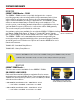
PRODUCT SAFETY INFORMATION • All personnel who may be expected to use this equipment must be thoroughly trained in its safe and proper use. • Before flowing water from this device, check that all personnel (fire service and civilian) are out of the stream path. Also, check to make sure stream direction will not cause avoidable property damage. • Become thoroughly familiar with the hydraulic characteristics of this equipment, and the pumping system used to supply it.
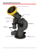
COBRA EXM2 MONITOR FEATURE CALLOUTS X-Stream Series Master Stream Nozzle Double Race Bearings 2.
SYSTEM COMPONENTS MONITOR COBRA™ EXM2 Monitor – 7200X2 The COBRA™ EXM2 monitor is specially designed to be compact providing a greatly reduced swing radius. Unique waterway swivel joints utilize stainless steel thrust rods, and needle roller thrust bearings, for unprecedented durability in a range of applications. The COBRA™ EXM2 utilizes a cast vaned waterway to minimize large-scale turbulence.
CONTROL Joystick Controller - 7030X2 The Joystick Controller can be mounted inside the apparatus cab to control all monitor functions, including oscillation, stow and deploy.The monitor direction (both vertical and horizontal movement) is changed by moving the joystick in the desired direction of travel. The up-down and left-right motions can be operated simultaneously with pressure sensitive speed, moving the monitor faster or slower depending on how far the joystick is pushed and pulled.
MONITOR & VALVE ACCESSORIES Position Feedback Display – 7051X2 All EXM2 monitors come with Absolute Position Feedback sensors.These sensors provide constant feedback to the monitors’ processor even when the monitor is moved via manual override. This information is then transmitted to the Position Feedback Display.
• CAN wire type and shielding: Twisted shielded pair - 105°C 150V (Belden 9841 series or equivalent) • Shield Drain: Connect shield/drain to pin C of J1939 connector Recommended electrical requirements for the EXM2 input devices– • Power and Ground wire gauge and length: 18-20 AWG Cross link or equivalent 105°C 150V up to 150 ft. (45.7 m) • Maximum input controller amperage draw: 500mA • Monitor is terminated and must be at the end of the main CAN line.
• The monitor will use a CAN line to communicate with other EXM2 components. Connect the monitor pigtail 1 to CAN bus. • Supply power to the monitor by connecting the two red and two black leads from the 8 pin connector to an appropriate power source. Install one 20 Amp fuse in line to both positive power leads for a 12V system (10 Amp for 24V system) to protect the monitor electrical components. • Refer to the respective plug figures for information on the plugs’ pins.
Proximity Sensor for Extended Travel: An OEM supplied proximity sensor is used only for extended travel functionality and is not necessary for standard monitor operation. The Cobra EXM2 is capable of vertical extended travel beyond the calibration point (straight up). An additional ground input is needed to enable this functionality.This functionality is intended to allow an OEM supplied proximity sensor to be used to enable or disable extended travel when the monitor is used with aerial applications.
Cable B – P/N 37550000 Monitor Pigtail included with EXM2 monitor Cable C – P/N 37544000 Valve Pigtail included with E14X/E16X actuator Cable D - P/N375440NT Valve Pigtail non-terminated harness for E14X/E16X valve actuator (optional) Cable E – EXM2 Extension Cable (optional) 12
Cable F – P/N 24196000 Splitter (optional) Cable G – P/N 24197000 CAN Termination Plug (optional) Cable H – P/N 37561000 Docking Station Pigtail included with EXM2 Hand Held pkg Cable J - P/N37551000 Gateway Pigtail included with EXM2 Hand Held pkg 13
EXM2 Wiring Connections E E E F CAN Splitter E F CAN Splitter F CAN Splitter C B EXM2 Monitor A 7051X2 EXM2 Position Feedback Module A Terminating Resister A 7010X2 EXM2 Panel Mount or 7030X2 EXM2 Joystick Controller (Both Factory Set as Primary) E14X/E16X Actuated Valve EXM2 Gateway EXM2 Handheld Controller and Docking Station 7015X2 EXM2 Handheld Package (Factory Set as Secondary) Valve comes terminated from factory EXM2 monitors come terminated from factory and should always be at end
Handheld Controller, Gateway and Docking Station Docking Station • Using the Docking Station template located at www.elkhartbrass.com, drill 6 #7(0.201” 5.1mm) drill holes as shown through the panel. • Mount the Docking Station with six (6) 10-24 screws using blue Loctite 242 or equivalent. The controller has a 0.375 thread depth. Torque screws to 50-60 in-lbs (5.66.8 Nm). • Supply power to the Docking Station by connecting the plug leads shown to an appropriate unswitched power source.
Joystick Controller – • Using the Joystick Controller template located at www.elkhartbrass.com, drill all holes as shown through the panel. • Mount the Joystick Controller using 4 3/8” fasteners secured with blue Loctite 242 or equivalent. • Connect plug 2 to the appropriate CAN line. 1 Joystick Plug Information 2 • Supply power to the Joystick by connecting the red (+) and black (-) leads coming from plug 1 to an appropriate power source.
Position Feedback Display – • Using the Position Display template located at www.elkhartbrass.com, drill the two 11/64” holes as shown through the panel intended for mounting the display. • Mount the Position Feedback Display using two (2) 6-32 x ½” fasteners secured with blue Loctite 242 or equivalent. Torque to 50-60 in-lbs (5.6-6.8 Nm). • Connect plug 2 to the appropriate CAN line.
Nozzles – • Ensure there is a gasket inside the nozzle swivel. • Hand tighten the nozzle onto the monitor discharge. • Loosen the swivel to reposition the nozzle as shown. • Tighten the nozzle swivel with a spanner wrench. • Supply power to the nozzle by connecting the monitor and nozzle harness connectors.
Installation Step 2: Configure the EXM2 System NOTE: EXM2 systems using consisting of a monitor and one Panel Mount or Joystick, a handheld with gateway, a position display, and an E14x or E16X actuated valve do not require configuration. EXM2 monitors come factory set for CAN termination and must be at the extreme end of the main CAN line. See options for CAN wiring and termination on page 14.
Installation Step 3: Calibrate the EXM2 System NOTE: If calibration was completed during the previous step, skip step 3. After successfully installing the system, the system must be calibrated. Calibrating the EXM2 monitor’s horizontal and vertical rotation is a necessary step for EXM2 systems. If it was necessary to configure your system using Wi-Fi, calibration can also be done via the Wi-Fi interface. See the EXM2 System Configuration Manual (P/N 98612000) for configuration instructions.
• Release the PRESET button. The horizontal axis is now calibrated. • Calibrating Vertical Rotation - (Optional) The Vertical calibration point is factory set at 90° (straight up). This is the position needed when wiring for extended travel (see Operating Instructions E), or when using a Position Feedback Display. This calibration will establish the highest vertical travel point of the monitor and allow rotation in the downward direction the total range specified during system calibration.
Calibrate Valve NOTE: LEDs flashing above the closed & open buttons on an input controller indicate that the valve has not been calibrated. If an Elkhart Brass Unibody valve is being used in your system, calibrate it at this time by first placing the valve in a half open position using the manual override, and then pressing and holding the CLOSE and PRESET buttons on any controller until the valve calibration begins.
OPERATING INSTRUCTIONS A. Button / Joystick Operation • OSC (OSCILLATE) – Used to set automatic motion of the monitor • POWER – Turns Hand Held controller on and off. • STREAM – Moves the nozzle in order to flow a straight stream of water (See step I, Oscillation for directions) • AUX (AUXILIARY) – Used for various operations including light operation, etc.
• Input Controller LEDs (General) • STOW LED • Lit solid = monitor has been stowed and is now at its stow position. • Flash = monitor is moving to its stow position. • DEPLOY LED • Lit solid = monitor has been deployed and is now at its deploy position. • Flash = monitor is moving to its deploy position • CLOSE LED • LEDs flashing above both the open & close buttons indicate that the valve needs to be calibrated.
• Blink meanings: • Green, Blue, or yellow blinking in a 1 blink continuous pattern indicates at least one of the following: • the monitor is moving • valve is moving • a button is being pushed on this panel mount. • Magenta blinking indicates that the handheld and it’s associated monitor are in setup or update mode. • Red blinking indicates handheld is in pairing mode. • Red-yellow = RF is paired, but not currently communicating to any other RF device.
• Red = RF is not paired (LED is solid) or Handheld is trying to pair (Led is blinking) • Blink meanings: • Green, Blue, or yellow blinking in a 1 blink continuous pattern indicates at least one of the following: • the monitor is moving • valve is moving • a button is being pushed on this panel mount. • Joystick STATUS LED • Color meanings: • Off = Joystick is not powered • Green = normal operation, monitor Wi-Fi is off.
D. Re-calibrating Horizontal and Vertical Rotation Calibrating the EXM2 system’s horizontal and vertical rotation is a necessary step for EXM2 systems of all types. The calibration points serve as a starting point for all other motion limits and commands entered to the EXM2 system. If not properly calibrated, the system may not operate correctly.
F. Extended Travel The Cobra EXM2’s maximum vertical travel is now dependent on the state of an additional input to position 4 of the 8-pin monitor power connector.This input allows the attachment of an OEM provided proximity sensor to trigger an open or grounded state of operation.The discharge vertical rotation limits from the horizontal center line (discharge parallel to the ground) for the proximity sensor input state are shown in the table below.
• Lower-Left Keep-Out Zone – The Left Keep-Out Zone will prevent the monitor from moving down and to the left into a specified zone (reference figure 1). • Put the EXM2 system into the Setup Mode (reference Part B of the Operating Instructions section) • Move the monitor to the top right corner of the keep out zone • The Keep-Out Zone should be set within the previously set monitor calibration points.
H. Motor Speed The speed of both the horizontal and vertical motors can be changed from something different than that set at the factory or during configuration of the EXM2 system. The monitor’s horizontal and vertical motors can be set to either Fast or Slow in one of four combinations. • Put the EXM2 system into the Setup Mode (reference Part B of the Operating Instructions section). • Press the OSCILLATE button to cycle through the various motor speed combinations.
M. Valve Operation with Controllers • OPEN – opens the valve. If the button is released, the valve will remain in the current position until another valve operation is performed. • In order to initiate auto-travel open, press and hold the OPEN button, then press and release the CLOSE button, then release the OPEN button. The valve will then auto-travel to fully open. • CLOSE – closes the valve.
MAINTENANCE INSTRUCTIONS Preventive Maintenance The complete monitor and control system should be inspected during each apparatus check. Careful inspection for damage to the monitor, valve or nozzle is especially important after use of the COBRA™ EXM2 monitor in emergency operations.
TROUBLESHOOTING GUIDE Understanding System LEDs • Monitor LEDs • The STATUS LED blinks yellow if an error occurred that caused the monitor to report a significant Diagnostic Trouble Code and go into safe mode. (The reported error is described through the EXM2 web interface accessed over Wi-Fi.) The blink pattern indicates the condition. The blinks will continue until the monitor control box is reset (power-cycled).
Status Blink Pattern Reason for Safe Mode Solution 2 blinks continuous Not Calibrated Complete Installation Step 3 3 blinks continuous Sensor Failure Check wires of the sensor for any damage. Ensure the wires are completely plugged into the control module (Wiring diagram is located at www.elkhartbrass.com). Order a replacement at Elkhart Brass 4 blinks continuous. Sensor indicates that monitor is Check wiring diagram at moving in the opposite direction www.elkhartbrass.com for motors location.
• When not moving or pushing buttons with Wi-Fi off, the STATUS LED blinks a yellow pattern if an error occurred that caused the monitor to report a significant Diagnostic Trouble Code and go into safe mode. (The reported error is described through the EXM2 web interface accessed over Wi-Fi.) The blink pattern indicates the condition. The blinks will continue until the panel mount is reset (power-cycled).
SYSTEM SPECIFICATIONS 7200 EXM2 Monitor Max Flow Rating 1250 GPM (4731 LPM) Max Operating Pressure 250 PSI Continuous (17.2 BAR) 500 PSI Limited Duty (34.5 BAR) [50% / 1hr (30min on / 30 min off)] Inlet Size 3”-150# Flange, DN80-PN16 Flange, 4”-150# Flange, 3” NPT, 3” BSPT Outlet Size 2.5” Male NHT, 2.5” Male BSPP Travel V: -45° to +120°, H: L175° to R175° Movement Sealed Electric Motors Swing Radius 6” (152mm) Stow Height 16” (406mm) Weight 31 Lbs.
Handheld Controller - 7015 Input power Li-Ion 3.7V Battery Life 3 years Battery Charge Life Up to 24 hours operation before recharge required RF Power Output Meets FCC part 15 requirements for license free operation (See note on page 33) Controller Dimensions 7.54in(191.5mm) x 3.85in(97.8mm) X 2.38in(60.5mm) Controller Weight 1.3 lbs.(0.
Gateway Model: 7015X2GW FCC ID: QT8EXM2GW FCC Statements: Note: This equipment has been tested and found to comply with the limits for a Class A digital device, pursuant to part 15 of the FCC Rules. These limits are designed to provide reasonable protection against harmful interference when the equipment is operated in a commercial environment.
Handheld Model: 7015X2 FCC ID: QT8EXM2WH FCC Statement: Note: This equipment has been tested and found to comply with the limits for a Class A digital device, pursuant to part 15 of the FCC Rules. These limits are designed to provide reasonable protection against harmful interference when the equipment is operated in a commercial environment.
Elkhart Brass Manufacturing Co., Inc. 1302 W. Beardsley Avenue Elkhart, IN 46514 Tel. (574) 295-8330 Toll Free (800) 346-0250 Fax (574) 293-9914 www.elkhartbrass.com Email: eb.info@safefleet.