User manual Cooker hood ERC925SA & ERC926BA
WE’RE THINKING OF YOU hank you for purchasing an Electrolux appliance. T You’ve chosen a product that brings with it decades of professional experience and innovation. Ingenious and stylish, it has been designed with you in mind. So whenever you use it, you can be safe in the knowledge that you’ll get great results every time. Welcome to Electrolux.
safety information This manual explains the proper use of your new Electrolux cooker hood. Please read this manual carefully before using the product. This manual should be kept in a safe place for handy reference. This cooker hood is a domestic appliance which has been manufactured and tested to comply with Australian and New Zealand Standard AS/NZS 60335.2.31. Read the following carefully to avoid damage or injury.
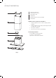
PRODUCT DESCRIPTION 1 2 1 3 4 5 6 Ceiling mount bracket Telescopic flue cover set Flue transition duct Wall bracket Main body and fan housing assembly Grease filters Additional items required for installation 2 • • • • ixings required to attach cooker hood body and anti F tilt points. Fixings required to attach ceiling mounting bracket and hood bracket to the wall. Duct tape or cable ties. Duct and accessories for external fluing.
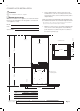
Dimensions 400mm 320mm 1120mm (Maximum) 480mm 38mm 500mm 895mm Fig. 4 Note: 1) The fan housing flue transition duct is 180mm in diameter. 2) Flue transition duct 180mm to 200mm (A shown below) is for external venting. (See page 13 for optional ducting accessories). A 200mm 180mm 180mm B Fig.
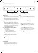
cooker HOOD INSTALLATION Warning! Refer to “Safety information” chapter. BEFORE INSTALLATION Before the installation of the appliance, record the information below from the rating plate. The rating plate is on the bottom of the appliance casing. 1. Using a spirit level mark a vertical centre line on the wall where the cooker hood is to be positioned, and a horizontal line at the cooker hood base position (refer to diagram below).
COOKER HOOD INSTALLATION (CONTinued) 3. Install flue cover wall mounting brackets with suitable fixings. Install suitable screws for cooker hood mounting points (to support a total weight of 30kg) to the wall as marked (Fig. 6). Depending on the preferred installation/ducting mode, follow step 5a or 5b below. 5a. Recirculating mode (Fig. 9) (optional kit AR900RK required) Using the centre line, secure the recirculating T-piece to the wall with suitable screws/fixings (optional kit AR900RK).
COOKER HOOD INSTALLATION (CONTinued) Fig. 11 6. Electrical connection Check that the installation complies with the standards of local building, gas and electrical authorities. Before connecting to the mains supply ensure that the mains voltage corresponds to the voltage on the rating plate inside the cooker hood. Fig.
COOKER HOOD INSTALLATION (CONTinued) Installation of telescopic flue covers Separate the inner and outer flue covers. Carefully reassemble the upper and lower flue covers sections by sliding the inner into the outer flue cover. Carefully lower the assembled upper and lower flue covers onto the top of the cooker hood body, and insert the flue cover into the cooker hood body approximately 5mm. Fix upper flue cover to the wall mounting bracket with screws supplied. Ensure that the upper section is extended.
USING THE COOKER HOOD S Fan Standby mode When connecting the cooker hood to the power supply for the first time or after power is returned after power outage, all symbols on the control panel will light up from left to right and a “beep” will sound once. Following this, the control panel goes to standby mode and the cooker hood will be ready for use. Turning on hood When the cooker hood is in standby mode, user can either press the or button to turn on the fan or light individually.
Maintenance and cleaning CAUTION! • Before maintenance or cleaning is carried out, the cooker hood should be disconnected from the main power supply. Ensure that the cooker hood is switched off at the wall socket and the plug removed. • • xternal surfaces are susceptible to scratches E and abrasions, so please follow the cleaning instructions to ensure the best possible result is achieved without damage. hese instructions must be followed to avoid a T fire risk.
TROUBLESHOOTING Problem Remedy The cooker hood will not start Check that the cooker hood is connected to an electrical supply Check that a fan speed has been selected The cooker hood is not working Check that the fan speed is set high enough for the task The grease filters are clean The kitchen is adequately vented to allow the entry of fresh air If set up for recirculation, check that the charcoal filter is still effective If set up for extraction, check that the ducting and outlets are not blocke
OPTIONAL DUCTING ACCESSORIES AR900RC AR900FS AR200F AR200WV Recirculation kit AR900RK AR200E Carbon filter AR900CF AR200FD Part numbers Description AR900FS Stainless steel exhaust cover AR900RK Recirculating Kit (180-150mm reducer, T-piece, carbon filters and 150mm semi rigid exhaust flue) AR900CF Carbon filter AR200RC 200mm G/Bond Roof Cowl AR200F 200mm G/Bond Flue 1200mm AR200WV 200mm Wall Vent AR200E 200mm Elbow duct AR200FD 200mm Semi rigid flexible exhaust flue (0.
Notes
Warranty FOR SALES IN AUSTRALIA AND NEW ZEALAND APPLIANCE: RANGEHOOD This document sets out the terms and conditions of the product warranties for Electrolux Appliances. It is an important document. Please keep it with your proof of purchase documents in a safe place for future reference should you require service for your Appliance. 1. You may not make a claim under this warranty unless the defect claimed is due to faulty or defective parts or workmanship.
Electrolux Home Products Australia telephone: 1300 363 640 fax: 1800 350 067 email: customercare@electrolux.com.au web: www.electrolux.com.au Electrolux Home Products New Zealand telephone: 0800 234 234 fax: 0800 363 600 email: customercare@electrolux.co.nz web: www.electrolux.co.nz The Thoughtful Design Innovator.