
Quick Start Manual


2
30" GAS SLIDE-IN RANGE INSTALLATION INSTRUCTIONS
(Models with Sealed Top Burners)
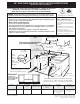
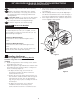
1 1/8"
(2,86 cm)
FRONT
OF
CABINET
F
Ref.
22 7/8" (58,1 cm) min.
23 1/4" (59,05 cm) max.
(see Note 4)
NOTE:
1. Do not pinch the power supply cord or the flexible gas conduit between the range and the wall.
2. Do not seal the range to the side cabinets.
3. 24" (61 cm) minimum clearance between the cooktop and the bottom of the cabinet when
the bottom of wood or metal cabinet
is protected by not less than ¼" (0,64
cm) flame retardant millboard covered
with not less than No. 28 MSG sheet
metal, 0,015"(0,4 mm) stainless steel,
0,024"(0,6 mm) aluminum, or 0,020"
(0,5 mm) copper.
30" (76,2 cm) minimum clearance when
the cabinet is unprotected.
4. For cutouts below 22 7/8"(58,1 cm),
appliance will slightly show out of the
cabinet.
5. Allow at least 19 ¼" (48,9 cm) clearance
for door depth when it is open.
A
D
C
B
Door Open
(see note 5)
Side panel
Figure 1
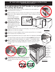
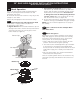
* IMPORTANT: To avoid cooktop
breakage for cutou t width (E
dimension) of more than 30 1/16"
(76,4 cm), make sure the appliance is
centered in the counter opening while
pushing into it. Raise leveling legs and
the rear adjustable wheels at a higher
position than the cabinet height (see
page 3), insert the appliance in the
counter and then level.
Make sure
the unit is supported by the
leveling legs at the front and
the wheels at the back and NOT
by the cooktop itself.
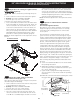
A. HEIGHT B. WIDTH C. COOKTOP
WIDTH
D. DEPTH TO
FRONT OF RANGE
E. CUTOUT WIDTH*
(Countertop and
Cabinet)
F. CUTOUT
DEPTH
G. HEIGHT
OF COUNTERTOP
35 5/8" (90.5 cm)
- 36 5/8" (93 cm)
30" (76,2 cm) 31½" (80 cm) 28 5/16" (71,9 cm) 30±1/16" (76,2±0,15 cm) 21 3/4" (55,2 cm) Min.
22 1/8" (56,2 cm) Max
24" (61 cm) Min. with
backguard
36 5/8" (93 cm) Max.
35 7/8" (91.1 cm)
Min.