
Installation Instructions


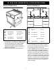


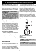
Table Of Contents

4
30” DUAL FUEL RANGE INSTALLATION INSTRUCTIONS
Product Dimensions
1. Measurement B varies according to the type
of installation: the minimum is obtained with-
out the rear spacers (see "Island installa-
tion") and the maximum is obtained for
traditional installation (slide-in installation -
with the rear spacers).
2. Measurement C refers to the open door.
Cabinet clearances
Clearance J can have the following values:
• J = 36” / 914 mm minimum clearance between
the top of the cooking surface and the bottom of
an unprotected wood or metal cabinet.
• J = 30” / 762 mm minimum when the bottom of
wood or metal cabinet is protected by not less
than 1/4-inch-thick flame-retardant millboard cov-
ered with not less than No. 28 MSG sheet steel,
0.015-inch-thick stainless steel, 0.024-inch-thick
aluminum, or 0.020-inch-thick copper. Clearances
from non-combustible materials are not part of the
ANSI Z21.1 scope and are not certified by CSA.
Clearances of less than 30'' should be approved
by the local codes and/or by the local authority
having jurisdiction.
A
760 mm 29” 15/16”
B
1
min: 654 mm
max: 658 mm
min: 25 3/4"
max: 25 14/16”
C
2
1186 mm 46 11/16"
D
min: 898 mm
max: 930 mm
min: 35 6/16"
max: 36 5/8"
E
min. 762 mm min. 30”
F
628 mm 24” 5/8
G
min. 508 mm min. 20”
H
min. 762 mm min. 30”
I
min. 457 mm min. 18”
J
see notes below
K
max. 330 mm max. 13”