ENGLISH Installation and user manual Tower models 5P 5P 5P 5P 650i 850i 1150i 1550i 1U Rack models 5P 5P 5P 5P Copyright © 2013 EATON All rights reserved.
Certification Standards UPS directives: • Safety: IEC 62040-1: 2008 (C2) • EMC: IEC 62040-2: 2005, VCCI • Performance: IEC 62040-3: 2010 CE mark (EN 62040-1: 2008 and EN 62040-2: 2006 (C1)) Class B emission level CISPR 22: 2005 + A2 2006 (EN 55022) Harmonics emission: IEC 61000-3-2 edition 3.2: 2009 Flickers emission: IEC 61000-3-3 edition 2: 2008 VCCI Notice The EC Declaration of Conformity is available upon request for products with a CE mark.
1. Introduction........................................................................................ 4 1.1 Environmental protection....................................................................................................4 2. Presentation....................................................................................... 5 2.1 Standard installations..........................................................................................................5 2.2 Tower rear panels...............
1. Introduction Thank you for selecting an EATON product to protect your electrical equipment. The 5P range has been designed with the utmost care. We recommend that you take the time to read this manual to take full advantage of the many features of your UPS (Uninterruptible Power System). Before installing 5P, please read the booklet presenting the safety instructions. Then follow the instructions in this manual.
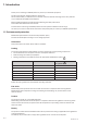
2.1 Standard installations Tower models D H W Description Weights (kg/lb) 5P 5P 5P 5P 7.52 / 16.60 9.93 / 21.90 10.91 / 24.10 15.95 / 35.20 650i 850i 1150i 1550i Dimensions (mm/inch) DxWxH 345 x 150 x 233 / 13.6 x 345 x 150 x 233 / 13.6 x 345 x 150 x 233 / 13.6 x 445 x 150 x 233 / 17.5 x 5.9 5.9 5.9 5.9 x x x x 9.2 9.2 9.2 9.2 Rack models D H W Description Weights (kg/lb) 5P 5P 5P 5P 8.6 / 19.00 13.8 / 30.40 14.64 / 32.70 19.36 / 42.
2. Presentation 2.
2.
2. Presentation 2.4 Control panel The UPS has a five-button graphical LCD. It provides useful information about the UPS itself, load status, events, measurements and settings.
2.5 LCD description Operation status Normal mode 100% 720W 800VA Load/equipment status 100% 10min Battery status Efficiency: ~98% Efficiency and load group information As default, or after 5 minutes of inactivity, the LCD displays the screen saver. The backlight LCD automatically dims after 10 minutes of inactivity. Press any button to restore the screen. The following table describes the status information provided by the UPS Note.
2. Presentation 2.6 Display functions Press the Enter ( ) button to activate the menu options. Use the two middle buttons ( through the menu structure. Press the Enter ( ) button to select an option. Press the or return to the previous menu. and ) to scroll button to cancel Menu map for Display Functions.
Description Load segments - Auto shutdown delay Available settings [Disable] [0s] [1 s] [2 s]…[65354 s] During a power outage, authorises to keep some equipment running while turning off other equipment. This feature allows to save battery power. In/Out settings Overload [10 %] [15 %] [20 %] ... [100 %] prealarm [105 %] Gives a warning when a predefined critical percentage of load is reached. Cold start [Disable] [Enable] Enables the product to be started on battery power. First cold start always disabled.
3. Installation 3.
3.2 Installation of tower models 3.3 Wall installation of rack models (650i R / 850i R / 1150i R) 1 2 2 1 620-00082-02-i (en) Page 13 ENGLISH 3.
3. Installation 3.4 Installation of rack models (650i R only) Follow steps 1 to 3 for rack mounting. 1 2 3 3 2 3.5 Installation of rack models (850i R / 1150i R / 1550i R) Follow steps 1 to 4 for module mounting on the rails. 1 1 2 3 2 3 4 4 The rails and necessary hardware are supplied by EATON.
3.6 Communication ports Connection of RS232 or USB communication port The RS232 and USB communication ports cannot operate simultaneously. 1. C onnect the RS232 (5) or USB (6) communication cable to the serial or USB port on the computer equipment. 5 2 1 6 2. C onnect the other end of the communication cable (5) or (6) to the USB (1) or RS232 (2) communication port on the UPS. The UPS can now communicate with EATON power management software.
4. Operation 4.1 Start-up and Normal operation To start the UPS: Verify that the UPS power cord is plugged in. The UPS front panel display illuminates and shows EATON logo. Verify that the UPS status screen shows . Press the button on the UPS front panel for at least 2 seconds. The UPS front panel display changes status to "UPS starting...". 5. Check the UPS front panel display for active alarms or notices. Resolve any active alarms before continuing. See "Troubleshooting" on page 18.
Low-battery warning • The and indicator illuminates solid. • The audio alarm beeps every three seconds. The remaining battery power is low. Shut down all applications on the connected equipment because automatic UPS shutdown is imminent. End of battery backup time • LCD displays "End of backup time". • All the LEDs go OFF. • The audio alarms stops. 4.
5. Maintenance 5.1 Troubleshooting Operation status Batteries disconnected Possible cause The UPS does not recognise the internal batteries The batteries are disconnected Action If the condition persists, contact your service representative Verify that all batteries are properly connected. If the condition persists, contact your service representative. Overload Power requirements exceeds the UPS capacity (greater than 105 % of nominal) End of battery life The end of the battery life is reached.
5.2 Battery-module replacement Safety recommendations The battery can cause electrocution and high short-circuit currents. The following safety precautions are required before servicing the battery components: • remove watches, rings, bracelets and all other metal objects from the hands and arms, • use tools with an insulated handle. Battery tray removal on tower models A-R emove the front panel. A B-D isconnect the battery block by separating the two connectors (never pull on the wires).
5. Maintenance Battery tray removal on rack models A-R emove the front panel. A B-R emove the left-hand side of the front panel by pushing the button and then by sliding the part. B C-D isconnect the battery block by separating the two connectors (never pull on the wires). C D-R emove the metal protection cover in front of the battery (two screws). D E-P ull the plastic tab to remove the battery block and replace it.
6.
Page 22 620-00082-02-i (en)