CREST ® d e e SHOWER DOOR INSTALLATION I NSTRUCTIONS n v i r L e s m e PLEASE REVIEW THIS ENTIRE MANUAL PRIOR TO INSTALLATION a R e Dr ghts © Ri All d e e in erv L s m e a R e r s D ght © Ri All ® MODEL #s SHDR-1760760-## SHDR-176076G-## ## = finish 01 - Chrome 04 - Brushed Nickel 06 - Oil Rubbed Bronze 09 - Satin Black G - Gray Glass left-hand door installation shown IMPORTANT! DreamLine® reserves the right to alter, modify or redesign products at any time without prior notice for the purpose of produ
This model is treated with DreamLine’s exclusive ClearMaxTM Glass technology. This is a specially formulated coating that prevents the build up of soap and water spots. Install the surface with the ClearMaxTM label towards the inside of the shower. Please note that depending on the model, the glass may be coated on either one or both surfaces. For best results, squeegee the glass after each use and dry with a ® soft cloth.
Section Title ClearMax™ Coating Information Warnings and General Preparaton Model Specific Preparation ® Tools Detailed Diagram of Shower Door Components Parts List Installation Steps Reversible 18" L-Bar™ and Top SafeStop™ Bumper Installation Bottom SafeStop™ Bumpers Installation Bottom Roller Assembly and Door Installation Handle and Vinyl Installation Reversible 18" L-Bar™ Feature Product Maintenance Troubleshooting Factory Parts Information d e e n v i r L e s m e a R e Dr ghts © Ri All d e e n v Symb
d e e n v i r L e s m e a R e r s D ght © Ri All WARNING DISCLOSURE STATEMENT IMPORTANT • • • DreamLine® reserves the right to alter, modify or redesign products any time without prior notice for product improvement and customer experience. Please refer to the model’s web page on DreamLine.com for the latest technical drawings, installation manuals, warranty information or additional product details.
! 1-3/4” minimum threshold REQUIRED: 1/2” Out-of-Plumb Adjustment on the Panel side only. Verify threshold and walls with a level ±0.0 d e e n v i r L e s m e a R e Dr ghts © Ri All Threshold must be level ® ©2020 DreamLine® All Rights Reserved Model Specific Preparation 1-3/4” minimum threshold ! ±0.0 Threshold must be level up to 1/2” adjustment for overall width or Out-of-Plumb conditions within the U-Channel (#09) on the panel side only.
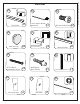
©2020 DreamLine® All Rights Reserved Tools Level Tape Measure Phillips Screwdriver Pencil Power Drill Silicone d e e n v i r L e s m e a R e Dr ghts © Ri All ® Drill Bit Ø1/8" (3mm) Drill Bit Ø3/16" (4mm) Safety Glasses Drill Bit Ø1/4" (6mm) Drill Bit Ø3/8" (10mm) Drill Bit Ø5/16" (8mm) Work Gloves Painter’s Tape Soft Head Hammer 3/8” thick wood/shims Hacksaw Razor Knife Mitre Saw Professional-grade Glass suction cup TOOLS PROVIDED FACTORY PART NUMBER 098001 098002 098003 098004 09800
CREST Shower Door Manual Ver 1 Rev 2 022020 Detailed Diagram of Shower Door Components ® d e e in erv L s m e a R e r s t D gh © Ri All 21 05 underside 02 10 11 20 01 07 09 08 ® e d si in 22 e r n i L e s m e a sR e r D ght © Ri l l A d e v 15 16 06 insi de left-hand door installation shown 5 ©2020 DreamLine® All Rights Reserved
©2020 DreamLine® All Rights Reserved Parts List 01 02 03 d e e n v i r L e x1 x1 s m e a R e Dr ghts © R05i 06 l Al ® Top Profile 04 Decorative Cap L-Bar™ Support Bracket (Reversible) x4 07 ST4.
©2020 DreamLine® All Rights Reserved Parts List 13 14 15 d e e n v i r L e x1 x1 s m e a R e Dr ghts © R17i 18 l Al ® SafeStop™ Bumper Plate (Top) 16 SafeStop Bumper PVC Insert (Bottom) SafeStop Bumper PVC Insert (Top) x2 19 ST4.
CREST Shower Door Manual Ver 1 Rev 2 022020 Installation Steps ® 1 d e e in erv L s m e a R e r s t D gh © Ri All Fig 1a left-hand door installation shown Top Guide Rail & 18” L-Bar Assembly sideview Parts Needed 01 x1 02 inside NOTE d e e in erv L s m Fig 1b e a R e r s t D gh © Ri l l A ® x1 03 Decide on the handing of the shower door based on your bathroom configuration. The left-hand door installation will be shown as an example throughout this manual.
CREST Shower Door Manual Ver 1 Rev 2 022020 2 d e e in erv L s m e a R e r s t D gh © Ri All ® Top *at model height ________” Middle ________” Bottom ________” d e e in erv L W s m e a R e Fig 2 r s t D gh © Ri l l A ® NOTE Tools Needed This model will provide up to 1/2” of adjustment for out-of-plumb conditions within the Vertical U-Channel (#09) on the panel side only.
CREST Shower Door Manual Ver 1 Rev 2 022020 3 After determining the handing of the installation: Only cut from the end of the Bottom Profile (#03) ® that will be installed on the door side of the opening. ! d e e in erv L s (W) (-) 1/16” = Finished Cut Length (L) Finished Opening m e a R e r s t D gh © Ri All The length to cut-off of the door side of the Bottom Profile (#03) will be (L): *Panel End *In this example, the Bottom Profile (#06) is shown for a right-hand door installation.
CREST Shower Door Manual Ver 1 Rev 2 022020 4 d e e in erv L s m e a R e r s t D gh © Ri All ® d e e in erv L s m e a R e r s t D gh © Ri l l A Fig 4 TIP ® Mark the position of the Bottom Profile (#06) on the threshold. Use a tape measure to keep the rail parallel with the outside edge of the threshold.
CREST Shower Door Manual Ver 1 Rev 2 022020 5 d e e in erv L s m e a R e r s t D gh © Ri All ® See NOTE d e e in erv L s m e a R e r s t D gh © Ri l l A Fig 5 NOTE ◾For installation into an Acrylic Threshold: drill an Ø1/8”(3mm) hole and use the ST4.2 x 40mm Countersunk Screw (#07) OR ◾For installation into a Tile Threshold: drill a Ø3/16”(4.76mm) hole up to the stud, drill an Ø1/8” (3mm) pilot hole into the stud and use the ST4.
CREST Shower Door Manual Ver 1 Rev 2 022020 6 d e e in erv L s m e a R e r s t D gh © Ri All ® unde rside Fig 6a underside of Bottom Profile (#06) d e e in erv L s m e a R e r s t D gh © Ri l l A Fig 6b ® Parts Needed 19 x3 Tools Needed 13 ©2020 DreamLine® All Rights Reserved
CREST Shower Door Manual Ver 1 Rev 2 022020 7 3 2 d e e in erv L s m e a R e r s t D gh © Ri All ® 1 ® e r n i L e s m e a Fig 7s R e r D ght © Ri l l A d e v left-hand door installation shown Parts Needed 09 x1 Tools Needed 14 ©2020 DreamLine® All Rights Reserved
CREST Shower Door Manual Ver 1 Rev 2 022020 8 ! Cut several 2” - 3” pieces of the the PVC Glass Spacer 1mm (#12). DO NOT install one long continuous® piece into the Bottom Profile (#06). d e e in erv L s m e a R e r s t D gh © Ri All 2” (50.
CREST Shower Door Manual Ver 1 Rev 2 022020 9 1 3ed e in erv L s m e a R e r s t D gh © Ri All 2 ® 01 02 d e e in erv L s m e a R Fig 9 e r s t D gh © Ri l l A ® Parts Needed 10 left-hand door installation shown NOTE 16 The vertical U-Channel (#09) is sent long to accommodate the finished opening conditions. Mark the U-Channel (#09) flush with the top guide rail and then cut to size in Step #11.
CREST Shower Door Manual Ver 1 Rev 2 022020 10 d e e in erv L s m e a R e r s t D gh © Ri All ® d e e in erv L s Figm 10 e a R e r s t D gh © Ri l l A ® left-hand door installation shown 17 ! Remove the 2” - 3” pieces of the PVC Glass Spacer 1mm (#12) from the Bottom Profile that were inserted in Step 08. These must be reinstalled before final installation of the panel glass.
CREST Shower Door Manual Ver 1 Rev 2 022020 11 d e e in erv L s m e a R e r s t D gh © Cuti Length (as measured in Step #9) (L) = Finished R All ® L L OR Fig 11 TIP Use a metal file to deburr the cut end d e e in erv L s m e a R e r s t D gh © Ri l l A ® Parts Needed 09 x1 Tools Needed 18 ©2020 DreamLine® All Rights Reserved
CREST Shower Door Manual Ver 1 Rev 2 022020 12 1 See NOTE 3d e e in erv L s m e a R e r s t D gh © Ri All ® 2 Fig 12 left-hand door installation shown ® e r n i L e s m e a sR e r D ght © Ri l l A d e v Parts Needed 07 ◾If a stud is present behind the wall: drill a Ø3/16”(4mm) hole up to the stud, NOTE TIP Cover the bottom profile with tape or cloth before drilling to prevent debris from getting into the channel. drill an Ø1/8” (3mm) pilot hole into the stud x8 ST4.
CREST Shower Door Manual Ver 1 Rev 2 022020 13 d e e in erv L s m e a R e r s t D gh © Ri All tooltip ® tooltip left-hand door installation shown Fig 13a ! Fig 13b d e e in erv L s m e a R e r s t D gh © Ri l l A When placing the Door Glass (#11) into the shower area, confirm the handle holes are on the correct side. Always use padding to protect the glass and shower surfaces.
CREST Shower Door Manual Ver 1 Rev 2 022020 14 d e e in erv L s m e a R e r s t D gh © Ri All ® 01 02 Fig 14a Fig 14b Widt h e Pa of nel G las Inlin s d e e in erv L s m e a R e r s t D gh © Ri l l A ® 21 ©2020 DreamLine® All Rights Reserved
CREST Shower Door Manual Ver 1 Rev 2 022020 Reversible 18” L-Bar™ and Top SafeStop™ Bumper Installation ® 15 d e e in erv L s m e a R e r s t D gh © Ri All Reversible 18” L-Bar™ Exploded View 02.5 02.7 02.3 Fig 15a d e v L-Bar™ Support Bracket, Reversible ® Item Description e r n i L e s m e a sR e r D ght © Ri l l TIP A right-hand 18” L-Bar™ installation shown Item 02.1 02.2 02.3 02.4 02.5 02.6 02.
CREST Shower Door Manual Ver 1 Rev 2 022020 16 1 2 ® n3e d e rv 4 i L e s m e a sR e r D ght © Ri All 5 6 *see NOTE Ø1/8” (3.17mm) drill bit Fig 16 d e e in erv L s m e a R e r s t D gh © Ri l l A ® NOTE Parts Needed 07 19 13 x2 x1 x1 Tools Needed Do Not fully tighten the Top SafeStop™ Bumper (#13) screw until instructed.
CREST Shower Door Manual Ver 1 Rev 2 022020 17 1 2 ® in3e d e rv L e s m e a sR e r D ght © Ri All 4 *see NOTE NOTE Tighten the screw before attaching the Top SafeStop™ Bumper PVC Insert(#14). Fig 17 d e e in erv L s m e a R e r s t D gh © Ri l l A ® TIP Parts Needed 14 x1 Tools Needed Secure the Top Guide Rail assembly to the outside surface of the Panel Glass (#10) with several pieces of painter’s tape until the silicone fully cures.
CREST Shower Door Manual Ver 1 Rev 2 022020 Bottom SafeStop™ Bumpers Installation 18 d e e in erv L s m e a R e r s t D gh © Ri All ® The surfaces need to be clean and free of debris before installing the SafeStop™ Bumpers. NOTE ! The 2 bottom SafeStop™ Bumpers (#15) must be installed to prevent the Door Glass from making contact with the walls.
CREST Shower Door Manual Ver 1 Rev 2 022020 19 d e e in erv L s m e a R e r s t D gh © Ri All ® Trim the Bottom Channel Insert (#18) to: W (-) 1/16” = L L L OR L Fig 19b W L Fig 19a TIP ! Use a metal file to deburr the cut end ® e r n i L e s m e a sR e r D ght © Ri l l A d e v Fig 19c Parts Needed 18 x1 Tools Needed To avoid glass-to-metal contact, insert a small piece (1/4” +/-) of the remaining PVC Glass Spacer 1mm (#12) between the end of the Bottom Channel Insert (#18) and the Panel
CREST Shower Door Manual Ver 1 Rev 2 022020 Bottom Roller Assembly and Door Installation 20 d e e in erv L s m e a R e r s t D gh © Ri All ® Fig 20a Fig 20b d e e in erv L s m e a R e r s t D gh © Ri l l A ® Fig 20c ! Parts Needed 22 x2 Tools Needed It is not necessary to fully disassemble the Bottom Roller Assemblies (#20).
CREST Shower Door Manual Ver 1 Rev 2 022020 21 d e e in erv L s m 3 e a R e r s t D gh !© i R All ® 1 2 pla ce a 24” pprox apa .
door glass panel glass Door Glass Too Low ! panel glass panel glass Fig 22a 1mm panel glass The top edge of the Door Glass (#11) should extend between 6mm and 10mm into the Guide Rail Inserts (#05). door glass ! Min. Door Glass Height door glass d e e in erv L s m e a R e r s t D gh © Ri All ® Max.
CREST Shower Door Manual Ver 1 Rev 2 022020 23 d e e in erv 2 L s m e a R e r s t D gh © Ri All ® 1 *Right end cap insid e Remove 3M™ Tape d e e Fig 23 in erv L s m e a R e r s t D gh © Ri l l A ® left-hand door installation shown NOTE Parts Needed 21 *Both the Left- (#21) and Right- (#21) Top Profile End Caps are shipped with the product. Use the Right Top Profile End Cap for the left-hand door installation as shown.
CREST Shower Door Manual Ver 1 Rev 2 022020 24 Handle and Vinyl Installation d e e in erv L s m e a R e r s t D gh © Ri All ® inside door glass panel glass Parts Needed 20 d e e n erv Fig 24 Li s m e a R e r s t D gh © Ri l l A ® NOTE Install the Handle (#20) so that the curvature matches the edge of the Door Glass (#11).
CREST Shower Door Manual Ver 1 Rev 2 022020 25 NOTE The surfaces need to be clean and free of debris before applying silicone. d e e in erv L s m e a R e r s t D gh © Ri All ® 24 Hours K PV 32 ! d e e in erv L s m e a R e r s t D25 gh Fig © Ri l l A ® Allow 24 hours for the silicone to cure before using the shower, then remove the painter’s tape that is securing the Top Guide Rail.
CREST Shower Door Manual Ver 1 Rev 2 022020 Reversible 18” L-Bar™ Feature d e e n v i r L e 3m s 4 e a R e r s t D gh © Ri All ® 1 2 outside 5 right-hand orientation 6 9 10 7 8 12 ed e in erv L s m e a R e r s t D gh © Ri l l A 11 ® 13 outside left-hand orientation 33 ©2020 DreamLine® All Rights Reserved
©2020 DreamLine® All Rights Reserved Product Maintenance BASES and BACKWALLS: To ensure long lasting life for your acrylic back walls: wipe them off after each use with a soft cloth. To clean the acrylic back walls use non-abrasive sprays or cream based cleaners. Avoid the use of aerosol spray cleaners. Never use abrasive cleansers, metal brushes or scrapers that could permanently scratch or dull the surface.
Problem/Symptom Suggested Solution •Check all shipping/packaging material for missing parts/components. •If not found, contact DreamLine Customer Support [1-866-731-2244] to order factory part replacement. Missing Parts Bottom Profile (#06) was cut too short or was cut from the wrong end during installation. •Contact DreamLine Customer Support [1-866-731-2244] to order factory part replacement.
CREST Shower Door Manual Ver 1 Rev 2 022020 Factory Parts Information d e e in erv L s m e a R e r s t D gh © Ri All CREST 60×72 SHDR-1760760-## ITEM # 01 02 03 04 05 06 07 08 07552148 09 BOLD digit indicates finish color: 1 = Chrome 4 = Brushed Nickel 6 = Oil Rubbed Bronze 9 = Satin Black 10 11 12 13 14 15 16 17 18 19 20 23 04154011-1930 / 04154041-1930 04154061-1930 / 04154091-1930 10036001 10036002 07550134 07021191 / 07024191 07026191 / 07029191 07050135 07021193 / 07024193 07026193 / 07029193
CREST Shower Door Manual Ver 1 Rev 2 022020 Factory Parts Information d e e in erv L s m e a R e r s t D gh © Ri All CREST 60×72 SHDR-176076G-## ITEM # 01 02 03 04 05 06 07 08 09 10 11 12 13 14 15 16 17 18 19 20 21a 21b 22 23 24a 24b FACTORY PART NUMBER 04236091-0904PF 07129152 095205 07559136 07550133 04237091-1524PF 092108 07552148 04154091-1930PF 10036003 10036004 07550134 07029191 07050135 07029193 07050132 094214 04238091-0887PF 092105 07229089 07551137 07551144 07329031 063004100-1886 07550152 0
d e e n v i r L e s m e a R e r s D ght © Ri All ® d e e in erv L s m e a R e r s D ght © Ri All ® TEL: 866-731-2244 FAX: 866-857-3638 DREAMLINE.COM For more information on DreamLine® Shower Doors and Enclosures please visit DreamLine.