Operator's Manual CRAFTSMAN+ 6 x 48" Belt 9" Disc SANDER/GRINDER WITH STAND Model No. 351.225950 CAUTION: Read and follow all Safety Rules and Operating Instructions before First Use of this Product. Sears, Roebuck and Co., Hoffman 2087.00 Draft (06/30/98) Estates, IL 60179 U.S.A.
Warranty ....................................... 2 Safety Rules .................................... 2 Unpacking ..................................... 3-4 4-5 Operation .................................... Maintenance .................................... 5-7 7 Espa_ol .................................... • Extension cords should have a grounding prong and the three wires of the extension cord should be of the correct gauge. 3 Assembly ..................................... Installation ..........
Refer to Figures 1 and 2. Check for shipping damage. If damage has occurred, a claim must be filled with carrier. Check for completeness. Immediately report missing parts to dealer. The grinder comes assembled as one unit. Additional parts which need to be fastened to grinder, should be located and accounted for before assembling.
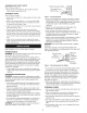
ASSEMBLE BELT DUST CHUTE Refer to figure 9, page 10. Properly Grounded Outlet __=_i} Grounding Prong. • Mount belt dust chute (Key No. 40) to platen using two washer head screws (Key No. 25). ASSEMBLE STAND 3-Prong Plug __'__ Refer to Figure 8, page 9. Figure 3 - 3-Prong Receptacle Install rubber foot (Key No. 4) by pressing onto all four legs (Key No. 3). • Plug must be plugged into matching outlet that is properly installed and grounded in accordance with all local codes and ordinances.
Extension Cord Length Wire Size .................................. A.W.G. Up to 25 ft..................................... 18 NOTE: Using extension cords over 25 ft. long is not recommended. MOTOR The sander/grinder is assembled with motor and wiring installed as an integral part of the tool. The electrical wiring schematic is shown in Figure 5. The 120 Volt AC permanently split capacitor motor has the following specifications: Horsepower (Maximum Developed) ................. 11/2 Voltage ..............
WARNING: Operation of any power tool can result in foreign objects being thrown into the eyes, which can result in severe eye damage. Always wear safety goggles complying with United States ANSI Z87.1 (shown on package) before commencing power tool operation. Safety goggles are available at Sears retail stores or catalog. CAUTION: SAFETY Rotate belt by hand to check tracking. Belt should ride centered on drive and idler drums. Adjust thumb nut (Key No. 75) as needed to center belt on drums.
USING MITER GAUGE Refer to Figure 9, page 10. • The miter gauge is used on both belt and disc tables. Use the miter gauge for securing the work and holding the proper angle while sanding. • Adjust angle by repositioning the miter gauge scale (Key No. 78) and locking it into place with knob (Key No. 79). • Check accuracy of miter gauge scale. • Use a combination square to adjust miter gauge square to disc. Indicator should be at zero. Loosen screw (Key No. 80) and reposition indicator if necessary.
SYMPTOM Motor will not start POSSIBLE CAUSE(S) CORRECTIVE ACTION 1. Low voltage 1. Check power line for proper voltage 2. Open circuit in motor or loose connections 2. Inspect all lead connections on motor for loose or open connection Motor will not start; fuses blown or circuit 1. Short circuit in line cord or plug 1. Inspect line cord or plug for damaged insulation and shorted wires breakers are tripped 2. Short circuit in motor or loose connections 3.
Model 351.225950 Figure 8 - Replacement Parts Illustration for Stand 1 \ 6 ; 3 KEY NO. PART NO. DESCRIPTION 1 1264.00 2 1265.00 Top frame Brace 3 1266.00 4 1267.00 5 STD533105 6 8428.00 5/1_'-18x W' Carraige bolt* 5/1_"-18Washer Head Hex Nut 7 STD835050 8-1.25 x 50mm Hex head bolts* 4 8 STD840812 8-1.25mm Hex nuts* 4 QTY.
Model 351.
KEY NO. KEY NO. PART NO. DESCRIPTION 46 47 8387.01 8658.00 Belt Table Asm. (Key Nos. 43-45) Motor Fan 1 1 48 49 50 51 8114.00 8388.00 8389.00 8390.00 Relay Bracket Indicator 6 x 12mm Dowel Pin 1 1 1 1 2 Forming Screw Capacitor Capacitor Cap 52 53 54 8391.00 8392.00 1822.00 Pivot Stop Bracket Drive Drum Platen 8-1.25 x 20mm Socket Head Bolt 1 1 1 6 1 2 55 56 STD852008 8393.
LIJADORA/ESIVlERILADORA CON PLATAFORIVlA • Use una cubierta protectora para el cabello, para sujetar el cabello largo. • Use zapatos • Use galas de seguridad que cumplan con ANSI Z87.1 de Estados Unidos. Los anteojos corrientes tienen solamente Correa de 15,2 × 121,9 cm de seguridad lentes resistentes con suelas antideslizantes. NO son anteojos de seguridad. Disco de 22,9 cm • Use una mascara para la cara o una mascara si la operaci6n de lijado produce polvo. para el polvo, Modelo No.
• • Evite el arranque por accidentes. de la herramienta enchufarla. est,. en la posici6n No fuerce la herramienta. a la velocidad AsegOrese que el interruptor OFF (apagado) Trabajarb, en la forma antes de m_.s eficiente para la cual se dise56. las manos alejadas G • Mantenga de las partes m6viles. • Nunca deje que una herramienta funcione sola. Descon_ctela y no se vaya hasta que se detenga completamente. • No trate de alcanzar demasiado lejos. Mantengase B firme y equilibrado.
MONTAJE DE LA MESA DEL DISCO Refierase • a la Figura 9, p_.gina 10. Adjunte la protecci6n del disco a la defensa del extremo (Clave No. 23) usando tres tornillos de cabeza de arandela Refierase (Clave No. 27). • Deslice con la ranura en el disco alineada ADVERTENCIA: con El motor ha sido diseSado el canal del polvo del disco (Clave No. 28) en la pro- la mesa del disco con los muSones adjuntos • • la mesa en la posici6n deseada y asegQrela sean menos que el voltaje especificado.
• Cuando se encuentra un receptb.culo de pared de 2 puntas, se Caballos de fuerza (al m_.ximo) ....................... Voltaje ......................................... 120 reglamentos locales. Amperios ........................................ 8,0 Hertz del National ADVERTENOIA: tricista calificado. Electric Este trabajo Code y con los c6digos debe ser ejecutado ........................................... por un elec- bipolar, Tal6n de tierra. Adaptador Enchufe si est,.
• AsegL_rese que todas las protecciones tamente Refierase La lijadora AsegL_rese que todas las partes movibles ninguna interferencia. • AsegL_rese que todos los sujetadores no se hayan soltado de correa de 15,2 cm y disco de 9" de Craftsman ha sido fabricada de aluminio fundido resistente y de hierro fundido para ofrecer estabilidad y una operaci6n sin vibraci6n. La correa de 15,2 x 121,9 cm y el disco de 9" de di_.
gire el perno prisionero en el sentido contrario alas manillas del reloj para mover la correa a la derecha yen el sentido de las manillas del reloj para moverla a la izquierda, hasta que avance centrada en el tambor impulsor yen el Ioco. Apriete tuerca hexagonal al mismo tiempo que se sujeta el perno prisionero en su lugar. Monte el canal del polvo de la correa de arandela. con tornillos AJUSTE DE LA POSICION DEL CONJUNTO Refierase la de cabeza DE LA CORREA a la Figura 9, p_.gina 10.
ACABADO DE DISCO ABRASIVO MANTENGA ,, El lijado del disco abrasivo se adapta bien cuando hay que acabar superficies planas peque_as y bordes convexos. • Si el corddn electrico est,. desgastado, c_.mbielo inmediatamente. • • Cambie los abrasivos • Cambie cualquier • • Mueva la pieza de trabajo a trav_s del lado de abajo (derecho) del disco abrasivo. El disco abrasivo se mueve m_.s r_.pido y remueve rial en el borde externo. Para obtener precisi6n, m_.
SINTOMA CAUSA(S) El motor no arranca 1. Voltaje bajo 1. Revise la energia para ver si tiene el voltaje apropiado 2. Hay un circuito abierto en el motor o hay conexiones sueltas 2. Inspeccione todas las conexiones de entrada en el motor para verificar si hay alguna suelta o abierta 1. Hay un cortocircuito el enchufe 1.
For the repair or replacement parts you need delivered directly to your home Call 7 am - 7 pm, 7 days a week 1-800-366-PART (1-800-366-7278) Para ordenar piezas con entrega domicillo - 1-800-659-7084 a For in-home major brand repair service Call 24 hours a day, 7 days a week 1-800-4-REPAIR (1-800-473-7247) Para pedir servicio de reparacion domicillo - 1-800-659-7084 For the location a of a Sears Parts and Repair Center in your area Call 24 hours a day, 7 days a week mmmmmm mmmmmm 1-800-488-1222 W