
Operator`s manual


RefertoFigures2- 5and75.
CAUTION:Donotattemptassemblyifpartsaremissing.
Usethismanualtoorderreplacementparts.
• Removeallcomponentsfromtheshippingcartonandverify
againstthepartslistonpage3.Cleaneachcomponentand
removeshippingpreservatives(coatings)asrequired.
• Afterselectinganappropriatebench,table,orlathestand,set
thebed(Figure75,No.1)towardsthefrontandtheleftside.
• Thewoodlatheisshippedfullyassembledexceptforthetail-
stockhandwheelandtheturningcenterswhichareselective-
lyemployedbaseduponthenatureofthewoodworkingtask.
• The12"toolrestmaybeexchangedforthe6"toolrestor
otherspecialtytypes,suchasbowl-turningrests,etc.
• Thetailstockhandwheelshouldbesecuredtothepushrod
usingthesetscrew.
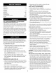
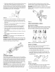
Lo 19mm
Hex
Wrenches III
Figure 2-Tools Needed for Assembly and Installation
• Examine the line cord (Figure 75, No. 17) to make sure
that the plug is in good condition and that the insulation
has not been damaged during transit.
MOUNTING LATHE TO BENCH
• Position the lathe assembly on top of a suitable stand or
bench. The headstock end should be close enough to a
side edge so that outboard operations can be performed
without difficulty.
• Verify that the bed is resting flat on the bench top. Mark
the mounting hole locations using the holes in the bed as a
guide. Move the lathe and drill four 3/8"holes through the
bench top. Place the lathe back in position and feed four
5/_x 2" carriage bolts through the holes in the bed. Secure
from underneath with flat washers, Iockwashers, and hex
nuts (not supplied).
STABILITY OF WOOD LATHE
If there is any tendency for the lathe to tip over or move dur-
ing certain cutting operations, such as cutting extremely
heaw pieces or long, out-of-round objects, the lathe should
be bolted down.
LOCATION OF WOOD LATHE
The lathe should be positioned so that neither the operator
nor a casual observer is forced to stand in line with the spin-
ning chuck.
INSTALLATION OF CENTERS
The spur center and the bearing center have Morse taper #2
to match the spindle and tailstock bores. To install the centers,
slide them into the bores with a firm, swift movement. They
will be further secured when a workpiece is squeezed
between the centers.
REMOVAL OF SPUR CENTER FROM SPINDLE
• To remove the spur center from the spindle, hold the left
spindle nut stationary with one of the 38mm spanners and
then use the other to unscrew the right nut until it forces
the center out of the spindle.
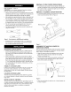
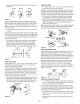
REMOVAL OF BEARING CENTER FROM RAM
• To remove bearing center from tail stock ram, turn hand-
wheel counterclockwise. Refer to Figure 3.
Handwheel
Bearing Center
\
Figure 3
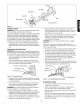
ALIGNMENT OF TAILSTOCK CENTER TO
HEADSTOCK CENTER
The spur center and the bearing center are used for spindle
turning and should always be in alignment. To align centers,
refer to Figure 4 and adjust as follows:
• Slide the tailstock toward the headstock so that the two
points of the centers are very close but not touching.
Tighten the tailstock lock.
• Loosen the hex bolt under the headstock assembly and
then rotate the entire headstock (left or right) until the
points of the centers are aligned.
_!_ Spur Center
r
Figure 4
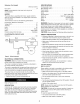
• When the wood lathe is ready for use, it should appear as
it does in Figure 5.
4