
Operator`s manual


. Place chip pan (Key No. 1) on top of supports, locat-
ing the bottom rail of the chip pan inside the sup-
ports.
. Secure chip pan to supports using hex head bolts
and flat washers (Key Nos. 2 and 3).
MOUNT MILL DRILL TO STAND
Refer to Figure 11.
Place mill drill on stand with mounting holes aligned.
Bolt mill drill base to stand with four hex head bolts and
four flat washers (Key Nos. 3 and 10).
MOUNT TABLE HANDWHEELS
Refer to Figure 9.
Thread handles (Key No. 11) into feed handwheels (Key
No. 12). Secure handwheels to the ends of longitudinal
lead screw (Key No. 35) and cross lead screw (Key No.
20) using set screws (Key No. 30).
INSTALL DRAWBAR AND ARBOR
Refer to Figures 7 and 8.
Insert draw bar (Figure 8, Key No. 52) into top of spin-
dle. Be sure that arbor and spindle taper are clean of all
dirt, metal chips, oil, etc. Insert chuck or face mill arbor
(Figure 7, Key Nos. 52 and 55) into spindle and rotate
arbor to engage spindle key in arbor keyway. Push
arbor into spindle and thread draw bar into end of
arbor. Use a wrench to tighten draw bar securely.
Refer to Figures 3, 4 and 5.
MOTOR
The 115/230 Volt AC motor has the following
specifications:
Horsepower (Continuous Duty) ................. 1
Voltage ............................... 115/230
Amps ................................. 16.2/8.1
Hertz ..................................... 60
Phase .................................. Single
RPM .................................... 1725
POWER SOURCE
The motor is designed for operation on the voltage and
frequency specified. Normal loads will be handled safe-
ly on voltages not more than 10% above or below the
specified voltage.
Running the unit on voltages which are not within the
range may cause overheating and motor burn-out.
Heavy loads require that the voltage at motor terminals
be no less than the voltage specified.
GROUNDING INSTRUCTIONS
WARNING: Improper connection of equipment
grounding conductor can result in the risk of electrical
shock. Equipment should be grounded while in use to
protect operator from electrical shock.
Check with a qualified electrician if grounding instruc-
tions are not understood or if in doubt as to whether the
tool is properly grounded.
This tool is equipped with an approved 3 conductor
cord rated at 300V. A qualified electrician should wire
appropriate 3-prong plug to mill drill line cord.
Grounding plug should be plugged directly into a prop-
erly installed and grounded 3-prong grounding-type
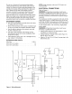
receptacle, as shown (Figure 2).
Properly Grounded Outlet --_;
Grounding Prong
3-Prong Plug II
Figure 2 - 3-Prong Receptacle
Do not remove or alter grounding prong in any manner.
In the event of a malfunction or breakdown, grounding
provides a path of least resistance for electrical shock.
WARNING: Do not permit fingers to touch the termi-
nals of plug when installing or removing from outlet.
Plug must be plugged into matching outlet that is prop-
erly installed and grounded in accordance with all local
codes and ordinances. Do not modify plug provided. If it
will not fit in outlet, have proper outlet installed by a
qualified electrician.
Inspect tool cords periodically, and if damaged, have
them repaired by an authorized service facility.
Green (or green and yellow) conductor in cord is the
grounding wire. If repair or replacement of the electric
cord or plug is necessary, do not connect the green (or
green and yellow) wire to a live terminal.
Where a 2-prong wall receptacle is encountered, it
must be replaced with a properly grounded 3-prong
receptacle installed in accordance with National Electric
Code and local codes and ordinances.
WARNING: This work should be performed by a quali-
fied electrician.
A temporary 3-prong to 2-prong grounding adapter (see
Figure 3) is available for connecting plugs to a two pole
outlet if it is properly grounded.
Grounding Lug
__ Make Sure
Adapter This Is
3-Prong Connected To
A Known
Ground
2-Prong Receptacle
Figure 3 - 2-Prong Receptacle with Adapter
4