
Operator`s manual


• Know your tool. Learn the tool's operation, applica-
tion and specific limitations.
• Use recommended accessories (refer to page 15).
Use of improper accessories may cause risk of
injury to persons.
• Handle workpiece correctly. Protect hands from pos-
sible injury.
• Turn machine off if it jams. Drill bit or cutter jams
when it digs too deeply into workpiece. (Motor force
keeps it stuck in the work.) Do not remove workpiece
until the mill drill is turned off, unplugged and the
spindle has stopped.
• Clamp workpiece or brace against column to prevent
rotation.
• Feed work into a bit or cutter against the direction of
rotation of bit or cutter.
• Use recommended speed for mill drill accessory and
workpiece material.
CAUTION: Think safety! Safety is a combination of
operator common sense and alertness at all times
when tool is being used.
WARNING: The operation of any power tool can result in
foreign objects being thrown into the eyes, which can
result in severe eye damage. Always wear safety goggles
complying with United States ANSI Z87.1 (shown on
package) before commencing power tool operation.
Safety goggles are available through your Sears catalog.
Refer to Figure 1.
Check for shipping damage. If damage has occurred, a
claim must be filed with carrier. Check for complete-
ness. Immediately report missing parts to dealer.
Carefully open crate and remove loose parts box.
Unbolt mill drill from shipping pallet and remove from
crate using heavy duty lifting equipment such as an
overhead crane.
WARNING: Be careful not to touch overhead power
lines, piping, lighting, etc. if lifting equipment is used.
Mill Drill weighs approximately 650 Ibs. Proper tools,
equipment and qualified personnel should be employed
in all phases of unpacking and installation.
Mill drill is shipped assembled except for certain parts
shipped loose in a wooden box. Locate and account for
the following parts:
A Drill chuck arbor
B %" Drill chuck with key
C Face mill arbor
D 3" Face milling cutter
E Three feed handwheels
F R8/MT3 Adapter
G Drawbar
Stand is shipped unassembled.
A
_ C D
/
/E F
Figure 1 - Unpacking
IMPORTANT: Table is coated with a protectant. To
ensure proper fit and operation, remove coating.
Coating is easily removed with mild solvents, such as
mineral spirits, and a soft cloth. Avoid getting solution
on paint or any of the rubber or plastic parts. Solvents
may deteriorate these finishes. Use soap and water on
paint, plastic or rubber components. After cleaning,
cover all exposed surfaces with a light coating of oil.
Paste wax is recommended for table top.
WARNING: Never use highly volatile solvents. Non
flammable solvents are recommended to avoid possible
fire hazard.
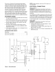
Refer to Figure 4, 7, 8, 9 and 11.
CAUTION: Do not attempt assembly if parts are miss-
ing. Use operator's manual to order replacement parts.
Mill drill must be mounted to a flat level surface. Use
shims or machine mounts if necessary. Do not mount
machine in direct sunlight. Heat caused by sunlight may
deform plastic parts on machine.
If stand is used, be sure to bolt mill drill to stand and
level stand to floor to minimize vibration. Use hex head
bolts, hex nuts and leveling pads (Figure 10, Key Nos.
8, 11 and 12) to align the mill drill. Tighten all nuts and
bolts that may have loosened in shipping. Secure mill
drill base to stand or bench.
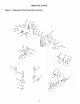
ASSEMBLE STAND
Refer to Figure 11.
• Place both supports (Key No. 5) upside down on
floor.
• Attach feet (Key No. 9) and plate (Key No. 7) to each
support using hex head bolts, washers and hex nuts
(Key No. 2, 3 and 4). Finger tighten fasteners at this
time.
• Repeat on other side of supports with feet and plate
(Key No. 14).
• Turn unit right side up.
• Install left and right panels (Key Nos. 6 and 13).
Gently spread supports so that tabs on panels fit
into slots located on supports.
• Secure all fasteners from steps 2 and 3.
3