Operator's Manual ® MILL DRILL WITH STAND Model No. 351.211970 CAUTION: Read and follow all Safety Rules and Operating Instructions before First Use of this Product. Sears, Roebuck and Co., Hoffman www.sears.com/craftsman 25140.00 Draft (02/19/07) Estates, IL 60179 U.S.A.
PREPARE Warranty .................................... SafetyRules............................... Unpacking.................................. Assembly................................. Installation ................................. Operation................................. Maintenance ............................... Troubleshooting .............................. PartsIllustrations andLists..................
• Know your tool. Learn the tool's operation, application and specific limitations. • Use recommended accessories (refer to page 15). Use of improper accessories may cause risk of injury to persons. • Handle workpiece correctly. Protect hands from possible injury. • Turn machine off if it jams. Drill bit or cutter jams when it digs too deeply into workpiece. (Motor force keeps it stuck in the work.) Do not remove workpiece until the mill drill is turned off, unplugged and the spindle has stopped.
. Place chip pan (Key No. 1) on top of supports, locating the bottom rail of the chip pan inside the supports. Check with a qualified electrician if grounding instructions are not understood or if in doubt as to whether the tool is properly grounded. . Secure chip pan to supports using hex head bolts and flat washers (Key Nos. 2 and 3). This tool is equipped with an approved 3 conductor cord rated at 300V. A qualified electrician should wire appropriate 3-prong plug to mill drill line cord.
Do not use a 3-prong to 2-prong grounding adapter unless permitted by local and national codes and ordinances. (A 3-prong to 2-prong grounding adapter is not permitted in Canada.) Where permitted, the rigid green tab or terminal on the side of the adapter must be securely connected to a permanent electrical ground such as a properly grounded water pipe, a properly grounded outlet box or a properly grounded wire system. NOTE: Using extension cords over 50 ft. long is not recommended.
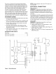
CAUTION: Always observe the following safety precautions: Refer to Figures 5, 7, 8 and 9. Craftsman 12-Speed Mill Drill Model 21197 is a ruggedly constructed machine providing accurate milling, drilling and boring capabilities. The fully enclosed R-8 spindle has heavy-duty tapered thrust bearings at top and bottom of quill, adjustable depth stop with scale, fine feed adjustment handwheel with .001" graduations and quill lock down handle for securely clamping spindle at desired depth.
Motor Spindle L D r Z Y X 4 3 i 2 A_ W _ I I U Figure 5 - Spindle Speed Chart Spindle RPM 120 Belt Location A1-4Z Tighten dial screw. TABLE STOP BLOCKS 190 B2-4Z 230 A1-3Y 285 C3-4Z Longitudinal travel can be limited to make repeated operations easier by using the table stop blocks (Key 370 B2-3Y No. 4o). 440 A1-2X 770 D4-3Y Table stop blocks are positioned to contact table stop bracket (Key No. 26) limiting table travel.
Rotating gib adjustment bolts (Fig. 9, Key No. 25) clockwise tightens dovetail ways. Adjust gib bolts until a slight drag is felt when moving the table with handwheels. Loosen bolts if table is too tight. I . Replace washer and spring cover knob. Rotate cover counterclockwise to tension spring. Rotate cover approximately three full turns and tighten cover knob. Release quill lock handle. ° Test spring tension by pulling down on crank handle (Figure 7, Key No. 19). Adjust spring tension as needed.
SYMPTOM POSSIBLE Motor does not run when start button is pushed 1. No power to motor 1. Check electrical connector and circuit breaker or fuse 2. Blown fuse on control box 3. Defective switch or contactor 2. Correct wiring problem and replace fuse 3. Replace defective parts Motor overheats 1. Low voltage to motor 2. V-belts too tight 3. Too deep or too fast a cut 4. Worn contacts in contactor 1. Check voltage 2. Tension belts properly 3. Reduce cut depth or speed 4.
Model 351.211970 Figure 7 - Replacement Parts Illustration for Head 36 33 32 31 35 ._.-._34 _ 38 _._L._ ""_._/_2_./28 _ •_u %h_, _'_\\ _l'_x" 41 6/'3/_:.. 6027 k, 61..... / / !i__f 59 /26 _ 46 _._.. ___42_4_. 23 22 _"" _ '_48 50 "_r'_ 47 49 : z!l _. 2 \ --. 62 17 64 16 L.. S " -... 14 ' -.... 52 --/_f 15-- _ "_P" " ,_\ 13 53 3 57_ '_\ _ "e_ \78 10 '\11 '" " ....
KEY NO. PART NO. DESCRIPTION KEY NO. PART NO. DESCRIPTION 1 2 3 4 05911.01 17147.00 07202.00 01043.00 Handle Handwheel 8-1.25 x lOmm Set Screw 6-1.0 x 8mm Set Screw 1 1 1 1 34 35 36 37 05901.01 04006.00 02683.00 16489.00 Head Adjusting Crank Handle 10-1.5 x 8mm Set Screw 1 1 1 5 6 05895.01 STD863510 Fine Feed Scale 5-0.8 x l Omm Pan Head Screw* 1 2 38 39 40 05866.01 15350.00 STD551025 Pinion Housing Knob 1 1 Retaining Clip ¼" Flat Washer* 1 1 7 8 05894.
Model 351.
KEY NO. KEY NO. PART NO. DESCRIPTION 1 38 17206.00 1 1 39 4O 41 17166.00 STD841620 17167.00 Motor and Key Pulley Cover 16-2.0mm Hex Nut* Spindle Quill 1 1 30206 J-N Taper Bearing 30mm Keyed Washer 1 1 42 43 44 17168.00 05910.00 00989.00 30-1.25mm Spanner Nut Depth Setting Knob 4 x 18mm Spring Pin 2 1 1 45 46 05975.00 STD835035 47 STD835016 Rod Bushing Rod Base 1 1 48 05973.00 6-1.0mm Hex Nut* 16-2.0mm Hex Jam Nut 1 1 49 5O 04076.00 STD863512 1 6 Depth Indicator Block 6-1.
Model 351.211970 Figure 9 - Replacement Parts Illustration for Base 3 31 41 / 19 2.... t _ 6 37 3! 24 33 48 16 35 15 38 14 36_!3 11 34 43 261 17 '_ / 25 31 48 44 12 12 11 \ 30 14 "_'"_ 49 46
KEY NO. PART NO. DESCRIPTION QTY. KEY NO. PART NO. DESCRIPTION Table Stop Bracket Table Lock Handle 1 4 Way Cover Lower Cover Plate 1 1 QTY. 1 17174.00 Base 1 26 05939.00 2 3 4 16378. O0 17175.00 00958.00 Column Column Cap 8-1.25 x 8mm Set Screw 1 1 1 27 28 29 15348. O0 05941.01 05942.00 5 6 7 STD851012 05926.00 15711.00 12mm Flat Washer* Rack 12-1.75 x 50mm Hex 8 1 8 3O 31 STD502503 STD835016 ¼-20 x _" Set Screw* 8-1.25 x 16mm Hex Head Bolt* 3 6 STD852012 17176.
Model 351.211970 Figure 10 - Replacement Parts Illustration for Control Assembly 3 7 45 / 43 T / .
KEY NO. KEY NO. PART NO. DESCRIPTION 1 1 3O 31 17205.00 17195.00 Fuse Holder Plate 1 1 4-0.7 x 8mm Round Head Screw 7 32 33 17196.00 16376. O0 Transformer 1 15337. O0 15338. O0 15339. O0 15310.00 Emergency Stop Switch Power Lamp 34 16398.00 Receptacle 3.5-0.6 x 10mm Oval Countersunk 2 4 Stop Switch Start Switch 1 1 1 1 35 17197.00 4.2-1.4 x 16mm Tapping Screw 2 8 9 10 17191.00 04076.00 15312.00 Control Box Housing Grommet Limit Switch Cord 1 2 1 36 37 38 17204.00 17198.
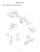
Model 351.211970 Figure 11 - Replacement Parts Illustration for Mill Drill Stand 9 _13 9 \ 14 \ 18
KEY NO. PART NO. DESCRIPTION 1 2 17413.00 STD840812 Chip Pan 8-1.25mm Hex Nut* 1 12 3 4 5 STD851008 STD835025 15301.00 8mm Flat Washer* 8-1.25 x 25mm Hex Head Bolt* 24 2O 2 6 7 15302.00 15303.00 Support Right Panel 8 9 10 11 15711.00 15304.00 STD835120 STD841217 Right Plate 12-1.75 x 50mm Hex Head Bolt Foot 8-1.25 x 120mm Hex Head Bolt* 12-1.75mm Hex Nut* 12 13 14 15306.00 15307.00 15308.00 Leveling Pad Left Panel Left Plate * Standard hardware item available locally. 19 QTY.
Your Home For repair - in your home - of all major brand appliances, lawn and garden equipment, or heating and cooling systems, no matter who made it, no matter who sold it! For the replacement parts, accessories and owner's manuals that you need to do-it-yourself. For Sears professional installation of home appliances and items like garage door openers and water heaters. 1-800-4-MY-HOME ® (1-800-469-4663) Call anytime, day or night (USA www.sears.com For expert home solutions and Canada) www.sears.