OWNER'S MANUAL MODELNO. 247.795850 CRRFTSMRN® Caution: ReadandFollow All SafetyRules and Instructions BeforeOperating This Equipment 5 HORSEPOWER 3 CUTTING STAGE MULCHING AND BAGGING CHIPPER-SHREDDER Assembly Operation CustomerResponsibilities Serviceand Adjustment Repair Parts SEARS,ROEBUCKAND CO., HoffmanEstates, IL 60179 U.S.A. 'rinted in U.S.A.
iMPORrANT _b o, AL SAFETY AND/OR PROPERTY OF YOURSELF AND OTHERS. READ AND FOLLOW ALL INSTRUCTIONS IN THIS MANUAL THIS SYMBOL POINTSOUT IMPORTANT SAFETYINSTRUCTIONSWHICH, IF NOTFOLLOWED,COULD ENDANGERTHE PERSONBEFOREATTEMPTING TO OPERATEYOUR CHIPPER-SHREDDER.FAILURE TO COMPLY WITH THESE INSTRUCTIONS MAY RESULTIN PERSONALINJURY. WHENYOU SEETHIS SYMBOL: ,{k HEEDITS WARNING. DANGER: Your chipper-shredderwas built to be operated accordingto the rules for safe operation in this manual.
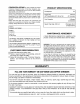
III. SERVICE 1. Use extremecarein handlinggasolineand other fuels. They areextremelyflammableandthe vaporsare explosive. a. Storefuel and oil in approvedcontainers,awayfrom heat and open flame,and out of the reachof children. Check and addfuel beforestartingtheengine. Neverremovegas cap or add fuelwhilethe engineis running. Allow engine to coolat leasttwo minutesbeforerefueling. b. Replacegasolinecap securelyand wipe off any spilled gasolinebeforestartingthe engineas it may causea fire or explosion. c.
CONGRATULATIONS on your purchase of a Sears Craftsman Chipper-Shredder. It has been designed, engineered and manufactured to give you the best possible dependability and performance. Should you experience any problem you cannot easily remedy, please contact your nearest Sears Service Center/ Department in the United States. We have competent, welltrained technicians and the proper tools to service or repair this unit. Please read and retain this manual.
TABLE OF CONTENTS CUSTOMER RESPONSIBILITIES ..................... 12, 13 STORAGE ................................................................ 14 SERVICE AND ADJUSTMENT ........................... 14-16 TROUBLE SHOOTING ............................................. 17 PARTS ORDERING/SERVICE ................................. 17 REPAIR PARTS--CHIPPER-SHREDDER ........ 18, 19 REPAIR PARTS--ENGINE ................................. 20-24 SAFETY RULES .........................................................
ASSEMBLY r" 3 INSTRUCTIONS IMPORTANT: This unit is shipped WITHOUT GASOLINE or OIL in the engine. After assembly, see operation section of this manual for proper fuel and engine oil recommendations. Flat ---=-//_ Washer | 1_ _ | 5/16" I.D. _,.-- Hex Lock Nut 5/16-18 Thread NOTE: To determine right and left hand sides of your chipper-shredder, stand behind the unit with the engine the farthest away from you. See figure 6.
Spacers_ HOWTO SET-UPYOUR CHIPPER-SHREDDER Housing MAKE Hex Bolt _hb Chute Deflector Hex Nut Hand Knob \\ \ // / / FIGURE2. Stop Washer Hopper Door \ Release Bar / // Upper Guide Assembly Bolt 8-3/8" Long Flat Washer Hex Lock Nut Inlet Guide FIGURE 3. Hopper Pivot Door Bar Hopper Assembly Upper Leaf Ramp Section Remove Truss Screw and Nut Guide (Assemble Assembly First) FIGURE 4. .Plunger FIGURE 5.
• To attachthe bag, placethe openingof the bag overthechutedeflectorso it completely coversthe chuteopening.Depressthe plungeron the draw- string,andpull on the drawstringuntilthe bagis tightaroundthe chuteopening.Releaseplungerto lockitintoposition.Seefigure5. OPERATION KNOW YOUR CHIPPER-SHREDDER READ THIS OWNER'S MANUAL AND SAFETY RULES BEFORE OPERATING YOUR CHIPPER-SHREDDER.
TO STOP ENGINE \ • Move throttle control lever to STOP position. See figure 6. No Larger Than 1/2" Diameter Or 1" Diameter (Maximum) • Disconnect spark plug wire and move away from spark plug to prevent accidental starting while equipment is unattended. See figure 6. HOW TO USE YOUR CHIPPER-SHREDDER Do not attempt to shred or chip any material other than vegetation found in a normal yard (i.e., branches, leaves, twigs, etc.).
GASAND OIL FILL-UP • To lower the hopper assembly, use one hand to grasp the handle at the top of the hopper assembly and lift slightly. Pull up on the release bar, and lower the hopper assembly to the ground. Release the bar. See figure 10. ---______ Hopper OIL (Packed with Unit) Only use high quality detergent oil rated with API service classification SF, SG or SH. Select the oil's viscosity grade according to your expected operating temperature. Colder _ ---.
• Attach spark plug wire and rubber boot to spark plug. See figure 13. Check the fuel level periodically to avoid running out of gasoline while operating the chipper-shredder. If the unit runs out of gas as it is shredding or chipping, it may be necessary to unclog the unit before it can be restarted, Refer to "Removing the Flail Screen" in SERVICE AND ADJUSTMENT section. • lever in FAST position NOTE: Primer may be needed to restart a warm engine after a short shut-down.
CUSTOMER MAINTENANCE SCHEDULE FILL IN DATES AS YOU COMPLETE REGULAR SERVICE RESPONSIBILITIES / DATES SERVICE p- to 4 Oil Pivot Points a O n- */ Clean Shredder D,. Check Engine Oil 4 -_/ Change Engine Oil _J *J Service Air Cleaner ,,=, Clean Engine Cylinder _' 4' Spark Plug _ -_ Muffler _f _/ CHECK GENERALRECOMMENDATIONS _ AND DISCONNECT THE SPARK PLUG WARNING: ALWAYS STOP THE ENGINE WIRE BEFORE PERFORMING ANY MAINTENANCE OR ADJUSTMENTS, • Periodically are tight.
AIR CLEANER CLEAN ENGINE Clean engine periodically. Remove dirt and debris with a cloth or brush. Cleaning with a forceful spray of water is not recommended as water could contaminate the fuel system. The air cleaner prevents damaging dirt, dust, etc., from entering the carburetor and being forced into the engine and is important to engine life and performance. Never run your engine without pletely assembled.
STORAGE Prepare your chipper-shredder for storage at the end of the season or if the unit will not be used for 30 days or more. ,_ • Drain the fuel tank. • Start the engine and let it run until the fuel lines and carburetor are empty. • Never use engine or carburetor cleaner products in the fuel tank or permanent damage may occur. • Use fresh fuel next season.
Replace or sharpen blades. If sharpening, make certain to remove an equal amount from each blade. Reassemble in reverse order. Hairpin Clips, Clevis Pins _Hex Nuts, Washers Make certain blades are reassembled with the sharp edge facing the direction shown in figure 18 (sharp edge is assembled toward the slotted opening in the impeller assembly). Torque bolts and nuts to 250-350 inch pounds. SHREDDING BLADE The shredding blade may be removed for sharpening or replacement as follows.
NOTE:Usecautionwhenremoving thebladetoavoid contacting theweldboltsonthe housing. • Whensharpeningthe blade,follow the original angleof grindas a guide.It is extremelyimportant thateachcuttingedgereceivesanequalamountof grindingto preventan unbalanced blade.An unbalancedbladewill causeexcessivevibrationwhen rotatingat highspeedsandmaycausedamageto theunit. • Thebladecanbetestedfor balanceby balancing it ona roundshaftscrewdriver or nail.Removemetal fromthe heavysideuntilit is balancedevenly.See figure21.
TROUBLE SHOOTING PROBLEM POSSIBLE CAUSE(S) CORRECTIVE Engine fails to start • Fuel tank empty, or stale fuel. • Spark plug wire disconnected. • Engine not primed correctly. • Throttle control not in correct starting position. • Faulty spark plug. • Fill tank with clean, fresh fuel. • Connect wire to spark plug. • Follow priming instructions in operation section. • Move throttle control to FAST position. Loss of power; operation erratic • • • Spark plug wire Joose. Blocked fuel line or stale fue!.
SEARS CRAFTSMAN 5 H.P. CHIPPER-SHREDDER MODEL NO. 247.795850 Repair Parts 22 3231 \ 23 \ \ \ l 56 ! 47 t ! 57 51 \ 77 78 _6 _5 63 \ z6 5,_ 79 t 59 34 61 18 35
SEARS CRAFTSMAN 5 H.P. CHIPPER-SHREDDER MODEL NO. 247.795850 Repair Parts CEY _10. PART NO.
SEARS CRAFTSMAN 5 H.P. ENGINE MODEL NO. 143.955003 Repair Parts 135 \ \ // \ \ \ \ g 125 , 1 I I 2O
SEARS CRAFTSMAN 5 H.R ENGINE MODEL NO. 143.
SEARS CRAFTSMAN 5 H.P. ENGINE MODEL NO. 143.955003 Repair Parts KEY NO. PART NO.
SEARS CRAFTSMAN 5 H.P. ENGINE MODEL NO. 143.955003 Repair Parts KEY NO. PART NO. 310 313 325 327 341 342 370A 370B 360 36640 34080 29443 35392 36644 651010 36261 33107 640004 DESCRIPTION Dipstick Spacer Wire Clip Starter Plug Fuel Tank Bracket Screw, 1/4-20 x 7/8" Lubrication Decal Speed Control Decal Carburetor (Incl. 184) KEY NO. PART NO. 390 400 590736 36627 416 36085 417 650760 DESCRIPTION Rewind Starter Gasket Set (Incl. Items Marked PK in Notes) Incl.
SEARS CRAFTSMAN 5 H.P. ENGINE MODEL NO. 143.955003 Repair Parts PARTS LIST FOR CARBURETOR KEY NO. z_J 24 PART NO. -- 640004 1 2 4 5 6 7 16 17 631615 631767 631184 631183 640009 650506 632164 650417 18 25 27 28 29 30 630766 631867 631024 632019 631028 631021 31 35 36 37 40 44 47 48 631022 36045 640007 632547 640008 27110 630748 631027 DESCRIPTION Carburetor (incl.
tlANUALDEI 'ROPIErARIO NUMERO DE MODELO 247.795850 CRRFTSMRN® Precauci6n: Lea y observe todas las reglas y instrucciones de seguridadantes de operar este equipo 5 CABALLOS DE FUERZA 3 ETAPAS DE CORTE CUBRIDOR DE PAJA Y EMBOLSADOR PICADO RA- DESM EN UZADO RA Armado Operacibn Responsabilidades del Cliente Servicio y Ajuste Piezas de Reparacibn SEARS,ROEBUCKAND CO., HoffmanEstates, IL 60179 U.S.A. )reso en U.S.A.
IMPORTANTE _) REGLAS DE SEGURIDAD A EVITARPELIGROS PARAELOPERADOR Y OTROS.LEALASSIGUIENTES INSTRUOOIONES DEESTEMANUALANTESDEINSTALAR EL EQUIPODEILUMINACION.FALTADEOBEDECER ESTASINSTRUCCtONES PUEDE RESULTAR EN DA_IOPERSONAL. ESTESIMBOLOINDICAINSTRUCCIONES IMPORTANTES PARASU SEGURIDAD.DEBEN SEGUIRSE RIGUROSAMENTE PARA AL CUANDO VEAESTESIMBOLO_IjPRESTE ATENC!ON A SUADVERTENCIA. PELIGRO: que concualquierm_quina,error o falta de cuidadopor partedel operadorpuederesultaren lesiones I _1_ serias.
_11. NI_OS Accidentes trdgicos pueden suceder si el operador no est_ aierto a la presencia de nifios pequefios. Los nifios a menudo son atraidos por el picadora-desmenuzadora y por la actividad que ejecutan. Nunca suponga que los nifios permanecer_n en e! mismo sitio donde Ud. los vio hace poco. • Mantenga a los nifios ]ejos del _rea de trabajo y bajo ta supervisi6n de un adulto ademds del operador de la m&quina. • Este alerta y apague la unidad si algt_nnifio se acerca al 9,rea.
FELlClTAClONES ESPECIFICACIONES DEL PRODUCTO per su compra de una PicadoraDesmenuzadora Craftsman de Sears. Ha side diseSada, planeada y fabricada par proporcionade la confiabilidad y rendimiento mejor posible. Si tuviera alg5n problema que no se pudiera remediar facilmente, Ilame a su Centre/ Departamento de Servicio Sears mas cercano en les Estados Unidos. Tenemos tecnicos competentes, bien entrenades y tas herramientas adecuadas para servir o reparar esta unidad. Per favor lea y guarde este manual.
TABLA DE MATERIAS -3 p Arandela plana _ ( 5/16" de didmetro _ _ interno _1 J Contratuerca hexagonal de rosca de 5/16-18 REGLAS DE SEGURIDAD ......................................... 2 ESPECIFICACIONES DEL PRODUCTO ................... 4 ACUERDO DE MANTENIMIENTO ............................. 4 RESPONABILIDADES DEL CLIENTE ....................... 4 GARANTIA ................................................................. 4 ACCESORIOS ............................................................
INSTRUCCIONES ARMADO DE IMPORTANTE: Esta unidad se envfa SIN GASOLINA O ACEITE. Despu_s det armado, vea la seccion de operaci6n de este manual para las recomendaciones del combustible y aceite del motor adecuados. NOTA: Para determinar los lades de mane derecha e izquierda de su picadora-desmenuzadora, col6quese detr_.s de la m_.quina con el motor atejado de usted. Ver la figura 6.
Puerta pivote de la Conjunto de la tolva SUJETANDO EL CONJUNTO DE LA TOLVA Su picadora-desmenuzadora ha sido enviada con la secci6n superior de la rampa de hojas sujeta al con"<-junto de la tolva. Vea la figura 4. Sujete el conjunto de la tolva al conjunto de la gu_a superior como sigue. Asegdrese de colocar las cabezas de todos los tornilLos de mdquina de refuerzo dentro del conjunto de la tolva.
OPERACION OONOZCASU PICADORA-DESMENUZADORA LEA ESTE MANUAL DEL PROPIETARIO Y LAS REGLAS DE SEGURIDAD ANTES DE OPERAR SU PICADORA-DESMENUZADORA Compare las ilustraciones con su picadora-desmenuzadora para familiarizarse con la ubicaci6n de varios controles y ajustes. Guarde este manual para referencia futura.
PARAAPAGAREL MOTOR • Mueva el acelerador figura 6. a la posici6n M_s pequeho que 1/2" de didmetro (Recomendado) 1" de didmetro STOP. Yea la • Desconecte el cable de la bujfa y alejelo de la misma para evitar un arranque accidental mientras el equipo no este atendido. Vea la figura 6. (M_ximo) ,_ COMO USAR SU PICADORADESMENUZADORA No trate de picar o desmenuzar cualquier material diferente de vegetaci6n que se encuentra en cualquier patio normal (por ej., ramas, hojas, ramitas, etc.).
cual se descarga el material, es posible que la cuchilla de desmenuzar y/o las cuchillas de picar esten desafiladas y tengan que ser afiladas o reemplazadas. Refierase a la secci6n de Servicio y Ajuste. • Para bajar el conjunto de la tolva, use una mano para asir al manija en la parte superior del conjunto de la tolva y lev,_ntela ligeramente. Tire de al barra de desenganche, y baje el conjunto de la tolva al suelo. Suelte la barra. Vea la figura 10.
Tanque de GAS • Quite la tapa de combustible y Ilene el tanque con aproximadamente 4 cuartos de gasolina de autom6vil, limpia, fresca, sin plomo, de alto grado. NO USE Etilo o gasolina de alto octano. Asegt_rese de que el contenedor este limpio y libre de 6xido o parficulas extraSas. Nunca use gasolina que este rancia pot haberse almacenado por un periodo largo en el contenedor. Vuetva a colocar la tapa de combustible.
• Tire de la cuerdacon un movimientodel brazo r&pido,continuoy pleno. Sujetefirmementela manJjade encendido.Permitaquela cuerdase enrollelentamente.No permitaque la manijade encendido saltehaciaatr&scontrael encendido. NOTA: Para prevenirque la mAquinase deslice, coloquesupiecontrael neumAtico. • Repitalas dos instrucciones anterioreshastaque el motordispare. NOTA:Si el motornodisparadespu_sde tresintentos,presioneel bot6ndelcebadordosvecesy tirede la cuerdaotravez.
minutos antes de revisar el nivel de aceite.Con et nivel de la picadora-desmenuzadora el aceite debe Ilegar hasta la marca FULL (LLENO) en la varilla para medir la profundidad de Ilenado de aceite (Refi_rase a la figura 12). Cambie el aceite del motor despu_s de las primeras cinco horas de operacion, y cada veinticinco horas subsecuentemente: RECOMENDACIONESGENERALES MOTOR Y DESCONECTE EL CABLE DE ADVERTENCIA: SIEMPRE LA BUJIA ANTES DE APAGUE EFECTUAREL CUALQUiER MANTENIM|ENTO O AJUSTES.
Base BUJIA Filtro Prefiltro Tuerca de mariposa La bujia deberia limpiarse y la distancia fijada nuevamente a .030" por Io menos una vez en la temporada o cada 50 horas de operaci6n. Vea la figura 17. Se recomienda el reemplazo de la bujia al comienzo de carla temporada_ Refi6rase a la lista de piezas del motor para el tipo correcto de bujfa. NOTA: No limpie a chorrro de arena la bujia. La bujfa deberia limpiarse rasp,_ndola con un cepUlo de alambre o lav_ndola con un solvente comercial.
ALMACENAMIENTO Prepare su picadora-desmenuzadora para almacenamiento al final de la temporada o si no se usara la unidad por 30 o m&s dias. • Nunca use productos limpiadores de motor o carburador en el tanque de combustible ya que puede ocurrir un daSo permanente. La prSxima temporada use combustible fresco.
i = i i i SERVICIO Y AJUSTE m AFILANDO 0 REEMPLAZANDOLAS CUCHILLAS ADVERTENCIA: SIEMPRE APAGUE EL MOTOR Y DESCONECTE EL CABLE DE LA BUJIA Y ALEJELO DE LA BUJIA ANTES DE EFECTUAR CUALQUIER MANTENIMIENTO O AJUSTES. CUCHILLAS DE LA PICADORA • Desconecte el cable de la bujia y al_jelo misma. • Quite el tamiz de la desgranadora en la secciSn anterior. EXTRAYEND0 EL TAME DE LA DESGRANADORA Extraiga el tamiz de la desgranadora si el Area de descarga se tapona.
CUCHILLA DE DESMENUZAR Puede retirarse la cuchilla de desmenuzar sigue. come • Desconecte misma. de la • Baje el conjunto Vea la figura 20. • Quite las seis contratuercas y arandelas de seguridad hexagonates de los pernos soldados de la cubierta usando una Ilave de 1/2". Separe la picadora-desmenuzadora en dos mitades. el cable de la buj/a y al_jelo • Cuando este afilando la cuchilla, siga el angulo original de esmerilado come guia.
LOCALIZACION PROBLEMA DE FALLAS ACCION CORRECTIVA CAUSA(S) POSIBLE El motor no se enciendet Perdida de potencia: operaci6n irregular • El tanque de combustible est,. vacio, o combustible rancio. • El cable de la bujfa esta desconectado. • El motor no ha sido cebado aclecuadamente. • El control del regulador no se encuentra en la posici6n de arranque adecuada. • Bujfa defectuosa. • Llene el tanque con combustible • El cable de la buj/a estA flojo.