f Sears maliiual CAUT _RRFTSN_N_ : . CHAJ IVE Ti E TILLE Read SAFETY RULES and iNSTRUCTIONS carefully o Assembly o Operating ®Maintenance . Repair Parts ........ 8F__._RS, and i m PART NO, , S_NS-SEARS i,,,i,ii ...................................... 770_7763 P, DEBU6-_ AND 03., Cht_I1. LI_MYI2!D, 60684 Toronto, IIIl/l' U_.A. Canada ,,,,.
FULL ONE YEAR WARRANTY For one year from the date of purchase, Sears will repai_ any defect workmanship in this TILLER at no charge If the TtLLER is used for commercial or rental purposes, thirty days from the date of purchase. Warranty service is available by contacting throughout this warranty ! in material applies or for onry the nearest Sears store or Service Center the United States..
IMPORTANT __is suggested that this manual be read in its entirety before attempting manual in a safe place for future reference and for ordering replacemen! This unit is shipped WITHOUT for proper fuel and amount,. Your tiller is a precision al! times GASOLINE orO1L After assembly, see operaiing piece of power equipment, not a l::lay thing Therefore SAFE OPERATION or operate section Keep this of this manual exercise extreme caution at PRACTICES FOR TILLERS 't.
UNDEX Warranty .................................... Safe Operation Practices ..................... Introduction ................................... Contents in Hardware Pack ......................... Tiller Identification ................................ Assembly Instructions ......................... Adjustments ..................................... Con trots ....................................... Engine Preparation ............................... 2 3 4 5 6 7 9 t0 13 Operation ..........................
E C G G J FIGURE 2, (SHOWN IN FULL SCALE) NOTE THE LETTERS LISTED BELOW WILL BE REFERRED TO THROUGHOUT THE FOLLOWING TEXT FOR EASIER HARDWARE IDENTiFICATION, LIST OF CONTENTS A B C D E F G H (2) (2) (2) (2) (t) (t) (3) (2) IN HARDWARE Shoulder Bolts Flat Washers BeltevitleWashe_s Hex Nuts 318-18 Thread Hex Screw 318-24 xi.
TILLER IDENTIFICATION Depth Slake Adj..
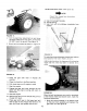
ASSEMBLY INSTRUCTIONS 1 D Handle Assembly A Place the handle assembly in p,:;s,'",k)n Or: Tip the tiller forward, counterweight Slide through titler as shown depth stake adjustment lock in place so it rests on depth stake up in figure 6, Pull pin on tiller to the tiller so that the holes in handle Ime up w_th holes in mountir, g bracket g Place flat washer (B} and bellevi_le washer (C) over shoulder on shoulder bolt (A) Place shou}der bolt and two washers through handle mounting holes and secure wit
Thread shift ferrule rod Secure in figure [0) on See figure ferrule other in gear shift 11) with er_.d of gear 10 llair lever pin cotter (as shown (K), FIGURE 8. H. Thread hex jam nut (P) on one end of gear shift rod, then thread gear shift rod into ball joint on the top of pivot horn assembly, 10 to 12 complete turns, approximately 1,,t,inch. See figure 9, FIGURE 11. K,, To assemble the handle adjustment lever.
2, Change oil after first 2 hours of operation and every 25 hours thereafter_ Check oil every 8 operating hours. FIGURE 13. Place throttle control lever up through the handle panel and secure with two self tapping screws (L), using a 1/4" fiat screwdriver.. See figure 14_ FIGURE 15. 3- Fill fuel tank with clean fresh regular grade of gasoline. See figure 16.. FIGURE 16. ADJUSTMENTS FIGURE 14.
Handle Adjustment Lever. (See figure t9 ) NOTE Figure 19 is _,iewed of handle panel from A_ Use if not enough free play B. Normal setting° C, Use If pin wilt not withdraw bracket. the bottom completely from FIGURE 17. 2 Pull the depth bar adjustment pin and move the depth stake all the way down. so the tines DO NOT" touch the ground See figure 18 3 Block the front wheels as shown in figure 18 FIGURE 19. To make the above adjustment loosen hex iocknut and reposition the rod in Hole A, B or C.
E CONTROLS Neutral (N)--Move See figure 22. lever to center detent Location and Use° t. Gear Shift Lever: The gear shift lever located in the center of handle Dane!. A is Forward (1 thru 5)--Move the lever to the left and forward for each gear See figure 2rl L_CAUTtON DO not attempt to shift gears unless engine is running° .i:: := FIGURE 23. F.
4 HandleAdjustment: The handleacljus[men_ releaseis located on the right hand handle bar_ See figure FIGURE 25, 3. Choke: The choke is located on the engine just below the air cleaner, To choke the engine pull the choke lever out., See figure 26. FIGURE 28. FIGURE 26. FIGURE 29. RGURE 27. FIGURE 30. 12 27.
S(;ue,:,_:'e _:nd place ;:,OSilionS up on hat]die adiustmen! ',he handle m one See _Igures 2_ 29 of B iever n_ne Egt 30 a,"_::_ 2,1 Drive position is when the klick pin is inserted into lhe _nside hole of ;,,,heel shall (hole Drive in wheelilub) as shown m figure position iS used for tilling 33 NOTE Figure 28 is viev,.ed filler for c;arily frc_r'n !he fr(.,n_ c)f FIGURE 33. TO START FIGURE _ 31.
TILLING TILLING HINTS Soil conditions are important for proper tilling The lines will not readily penetrate dry, hard soil This may contribute to excessive bounce and difficult handling of the tiller Hard soil should be moistened prior to tilling, Extremely clump_ wet soil will cause soil to bali up or When tilling in the Fall, all vines and tong grass should be removed. This will prevent vines trom wrapping around the tine shaft which slows tilling operation.
REMOVING AND REPLACING BELTS 1_ Remove bell cover remove three boils, two nuts and !wo fiat washers. See figure 36. _CAUTION HOT muffter in the area of belt cover Only remove the belt cover when engine is cool FIGURE 38, 4 Place the gear shift lever in one o! the forward gears (as far forward as possible) 5 Pull the idler pulley down by hand and remove the belt from idler pulley and transmission pulley See figure 39 FIGURE 36.
tion of your new engine and after each 25 hours of use thereafter to ensure proper lubrication of internal parts for trouble free operation and to prevent costly repair due to excessive wear. (Take care to remove dirt around li!ler plug.) Be sure oil level is maim tained full to point of overflowing Seefig{,re 42. _. FIGURE40, Oil Filler Oil Level Plug FIGURE 42_ TO change oil remove drain plug (figure 43) and tip the tiller forward while engine is warm. Replace drain plug.
air cleaner A. C. Take apart D, Wash element in detergent and squeezing similar to a sponge solution by B., FIGURE 44. E Wrap foam in cloth and squeeze dry. F. Coat element with two tablespoons of engine oil, squeeze to distribute and remove excess oil. See figure 45. G. Wipe air cleaner body remove excess oil. with same solution to INITIAL ADJUSTMENT.
A. The electrodes should be kept clean and free OF CARBON. The presence of carbon or excess oil will greatly deter proper engine performance. 1. Working outdoors, drain all fuel from the fuel tank° Use a clean dry cloth to absorb the small amount of fuel remaining in the tank, then run the engine until all fuel in carburetor is exhausted. DO NOT SMOKING, FIRE. FIGURE 47. 2.
NOTES 19
Repair Parts 5 H.P. TilUer ModeB 247.298770 55 -. 52 53 12 ;3 5t 29 _9 31 .oT_i O.e_0o,,oceo °4 Plastilube #1 grease, part no.
Repair Parts Transmission ' REF., i PART NO_ t NO T t i74t"0155 2 ! 04822 3 738-0379 4 7t4._0122 5 750..O379 6 7 7170210 750-.0378 8 9 04867 736-0259 10 1741-0t89 1 15 05034 _736-0329 !712-0138 1721-0102 736-02t9 736-0't69 7'12-0214 04872 736-0219 736-0169 7t0-041I !7t0-060t 18 19 20 21 22 23 i24 736-0242 29 3O 72! -0162 721-0102 71 2-0138 ................. "R I_-F'-]' DESCRIPTION ND Ball Bearing Transmission Ass / --,-q _,. Input Shaft 5,8- D_a Sq Key3!16×3'1 ].
Repair Parts 5°HoPo TiB_erModel 247°298770 4 5 2 I 4t 93 t3 73 \, 37 22
Repair Parts 5=H.P. Tiller ModeB 247.298770 REF. I No.I PART No.
Repair Parts 5oH.P, TiBBerModel 247°298770 I t ,/ 21 58 41 ..
Parts 5=H.P. Tiller Mode 247,298770 PART NO.I 1 2 3 4 5 6 7 8 NO.
TILLERACCESSORIES Hilling Plow (Must be used with "V" Bar Frame Adapter) Six Tang Cultivator (Recommended use of Depth Gauge Wheels) "V" Bar Frame Adapter (Recommended use of Depth Gauge Wheels) Four Shovel Cultivator(Must be used wilh "V" Bar Frame Adapter) Depth Gauge Wheels Tine Cultivating Shields Wheel Weights Tire Chains (13" x 5") 32" Angle Dozer Blade Front Hitch Mount (Required to mount 32" Angle Dozer Blade) 26
Repair Parts 5-H.P. CHAIN DRIVE TILLER MODEL 247.298770 ENGINE MODEL, 130202 TYPE 08"15-03 !72_6L3 5 337 ,_....
Repair Parts 5-H.Po CHAIN DRIVE TILLER MODEL 247,298770 ENGINE MODEL 130202 TYPE 0815-03 \ 3O4 24 \ 23 76 71 70 67 Z 75 373 _ 65,...
Repair Parts 5_H.P** CHAIN DRIVE TILLER MODEL 247.
Aepair Parts 5-H,P. CHAIN DRIVE TILLER MODEL 247.298770 ENGINE MODEL 130202 TYPE 0815-03 PARTS LIST FOR ENGINE REF, PART NO. NO, MODEL NO. 130202_0815-03 REF, DESCRIPTION Cylinder Ass'y. Bushing--Cylinder NOTE: Requires special tools for installation. Seal--Oil _ 89660 211542 Head--Cylinder 7 *270383 Gasket--Cylinder Head 8 294178 Breat her--Valve Chamber 9 *27549 Gasket--Valve Cover !0 93394 Screw--Breather Mtg. Sere !1 66578 Grommet_Breather Tube t2 *270080 Gasket_Crankcase _ .
Repair Parts 5-H.Po CHAIN DRIVE TILLER MODEL 247.298770 ENGINE MODEL 130202 TYPE 0815.o3 PARTS LIST FOR ENGINE "EF.j 200 201 202 203 204 DESCRIPTION NO. 221480 260661 260678 297718 230844 93838 260695 391737 22155! 221517 93491 391966 220680 222450 260478 221535 93496 391313 299410 93158 221511 93042 308 333 335 337 MODEL NO.
HOW TO ORDER REPAUR PARTS Sears ..... i i/ H i,, The Model Number wil! be found slamped chassis. Always mention the Model Number repair parts for your fiUer. i on a plate attached to the when requesting service or All parts listed herein may be ordered through SEARS ROEBUCK or SIMPSON SEARS LIMITED RETAIL or CATALOG STORE, manual WHEN ORDERING REPAIR PARTS, ALWAYS INFORMATION AS SHOWN lN THIS LIST. EL O. 247=298=(70 1 2_ 3.