Operator’s Manual ® 24” SNOW THROWER Model No. 247.883550 CAUTION: Before using this product, read this manual and follow all safety rules and operating instructions. • SAFETY • ASSEMBLY • OPERATION • MAINTENANCE • PARTS LIST • ESPAÑOL Sears, Roebuck and Co., Hoffman Estates, IL 60179, U.S.A. Visit our website: www.craftsman.com FORM NO.
TABLE OF CONTENTS Warranty Statement . . . . . . . . . . . . . . . . . . . . Page 2 Repair Protection Agreement . . . . . . . . . . . . . Page 3 Safe Operation Practices . . . . . . . . . . . . . .Pages 4-5 Safety Labels . . . . . . . . . . . . . . . . . . . . . . . . . Page 7 Assembly . . . . . . . . . . . . . . . . . . . . . . . . .Pages 8-11 Operation . . . . . . . . . . . . . . . . . . . . . . . .Pages 12-15 Service &Maintenance . . . . . . . . . . . . . .Pages 16-23 Off-Season Storage . . . . . . . .
REPAIR PROTECTION AGREEMENT Congratulations on making a smart purchase. Your new Craftsman® product is designed and manufactured for years of dependable operation. But like all products, it may require repair from time to time. That’s when having a Repair Protection Agreement can save you money and aggravation.
SAFETY INSTRUCTIONS WARNING DANGER This symbol points out important safety instructions which, if not followed, could endanger the personal safety and/or property of yourself and others. Read and follow all instructions in this manual before attempting to operate this machine. Failure to comply with these instructions may result in personal injury. When you see this symbol, HEED ITS WARNING! This machine was built to be operated according to the rules for safe operation in this manual.
SAFETY INSTRUCTIONS MAINTENANCE & STORAGE OPERATION • • • • • • • • • • • • • • • • • • • • Do not put hands or feet near rotating parts, in the auger/impeller housing or chute assembly. Contact with the rotating parts can amputate hands and feet. The auger/impeller control lever is a safety device. Never bypass its operation. Doing so makes the machine unsafe and may cause personal injury.
This page left intentionally blank.
SAFETY LABELS DANGER 1. KEEP AWAY FROM ROTATING IMPELLER AND AUGER. CONTACT WITH IMPELLER OR AUGER CAN AMPUTATE HANDS AND FEET. 2. USE CLEAN-OUT TOOL TO UNCLOG DISCHARGE CHUTE. 3. DISENGAGE CLUTCH LEVERS, STOP ENGINE , AND REMAIN BEHIND HANDLES UNTIL ALL MOVING PARTS HAVE STOPPED BEFORE UNCLOGGING OR SERVICING MACHINE. 4. TO AVOID THROWN OBJECTS INJURIES, NEVER DIRECT DISCHARGE AT BYSTANDERS. USE EXTRA CAUTION WHEN OPERATING ON GRAVEL SURFACES. 5. READ OPERATOR'S MANUAL.
ASSEMBLY NOTE: References to right or left side of the snow thrower are determined from behind the unit in the operating position (standing directly behind the snow thrower, facing the handle panel). REMOVING FROM CARTON 1. 2. 3. Cut the corners of the carton and lay the sides flat on the ground. Remove and discard all packing inserts. Move the snow thrower out of the carton. Make certain the carton has been completely emptied before discarding it.
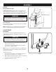
ASSEMBLY 3. 4. Position the chute assembly over the base. See Figure 3. Close the flange keepers to secure the chute assembly to the chute base. See Figure 4. The flange keepers will click into place when properly secure. NOTE: If the flange keepers will not easily click into place, use the palm of your hand to apply swift, firm pressure to the back of each. 5. a. Remove the flat washer and hairpin clip from the end of the chute directional control. b.
ASSEMBLY SET-UP Chute Clean-Out Tool A chute clean-out tool is fastened to the top of the auger housing with a mounting clip. See Figure 6. The tool is designed to clear a chute assembly of ice and snow. This item is fastened with a cable tie at the factory. Cut the cable tie before operating the snow thrower. Chute Clean-out Tool WARNING Never use your hands to clear a clogged chute assembly.
ASSEMBLY Chute Assembly The distance snow is thrown can be adjusted by changing the angle of the chute assembly. To do so: 1. Stop the engine by removing the ignition key and loosen the plastic wing knob found on the left side of the chute assembly. 2. Pivot the chute upward or downward before retightening the wing knob. See Figure 8. Auger Control WARNING Prior to operating your snow thrower, carefully read and follow all instructions below.
OPERATION Drive Control Auger Control Chute Assembly Electric Start Button Gas Cap Shift Lever Chute Directional Control Oil Fill Engine Controls Clean-Out Tool Recoil Starter Handle Electric Starter Outlet Primer Ignition Key Choke Control Augers Throttle Control Skid Shoe Figure 10 Now that you have setup your snow thrower, it’s important to become acquainted with its controls and features. Refer to Figure 10. SHIFT LEVER The shift lever is located between the lower handles.
OPERATION THROTTLE CONTROL DRIVE CONTROL/ AUGER CONTROL LOCK The throttle control is located on the rear of the engine. It regulates the speed of the engine and will shut off the engine when moved into the STOP position. DRIVE CONTROL RECOIL STARTER HANDLE This handle is used to manually start the engine. ELECTRIC STARTER BUTTON Pressing the electric starter button engages the engine’s electric starter when plugged into a 120V power source.
OPERATION CLEAN-OUT TOOL WARNING Never use your hands to clear a clogged chute assembly. Shut off engine and remain behind handles until all moving parts have stopped before using the clean-out tool to clear the chute assembly. The chute clean-out tool is conveniently fastened to the rear of the auger housing with a mounting clip. Should snow and ice become lodged in the chute assembly during operation, proceed as follows to safely clean the chute assembly and chute opening: 1.
OPERATION 5. 6. 7. Once the engine starts, release starter button. As the engine warms, slowly rotate choke control to the OFF position. If the engine falters, quickly rotate choke control back to FULL then slowly into the OFF position again. When disconnecting the extension cord, always unplug the end at the three-prong wall outlet before unplugging the opposite end from the snow thrower.
SERVICE AND MAINTENANCE ENGINE MAINTENANCE WARNING Before lubricating, repairing, or inspecting, disengage all controls and stop engine. Wait until all moving parts have come to a complete stop. FULL Checking Engine Oil 1. 2. 3. 4. 5. 6. Be sure engine is upright and level. Unscrew oil fill cap from oil filler tube and wipe dipstick clean. Screw oil fill cap back into oil filler tube. Tighten securely. Unscrew and remove oil fill cap from oil filler tube. Note oil level.
SERVICE AND MAINTENANCE Checking Spark Plug 2 Check spark plug yearly or every 100 operating hours 1. Clean area around spark plug. 2. Remove and inspect spark plug. 3. Replace spark plug if porcelain is cracked or if electrodes are pitted, burned or fouled with deposits 4. Check electrode gap with a feeler gauge and set gap to .030 (0.76mm) if necessary. See Figure 14. 5. Reinstall spark plug and tighten securely. 3 1 NOTE: A resistor spark plug must be used for replacement.
SERVICE AND MAINTENANCE SHAVE PLATE AND SKID SHOES The shave plate and skid shoes on the bottom of the snow thrower are subject to wear. They should be checked periodically and replaced when necessary. To remove skid shoes: 1. Remove the four carriage bolts and hex flange nuts which secure them to the snow thrower. 2. Reassemble new skid shoes with the four carriage bolts (two on each side) and hex flange nuts. Refer to Figure 17. To remove shave plate: 1.
SERVICE AND MAINTENANCE Chute Bracket If the spiral at the bottom of the chute directional control is not fully engaging with the chute assembly, the chute bracket can be adjusted. To do so: 1. Loosen the two nuts which secure the chute bracket and reposition it slightly. See Figure 19. 2. Retighten the nuts. Auger Control Refer to the Assembly section for instructions on adjusting the auger control cable. Skid Shoes Refer to the Assembly section for instructions on adjusting the skid shoes.
SERVICE AND MAINTENANCE 5. 6. 7. 8. Remove the frame cover from the underside of the snow thrower by removing four self-tapping screws which secure it. See Figure 22. Remove the belt as follows. Refer to Figure 23. a. Loosen and remove the shoulder screw which acts as a belt keeper. b. Unhook the support bracket spring from the frame. Remove the belt from around the auger pulley, and slip the belt between the support bracket and the auger pulley. See Figure 24.
SERVICE AND MAINTENANCE 3. 4. 5. 6. 7. Remove the belt as follows. Refer to Figure 25. a. Roll the auger belt off the engine pulley. b. Use a wrench to pivot the idler pulley toward the right. c. Lift the drive belt off engine pulley. Carefully pivot the snow thrower up and forward so that it rests on the auger housing. Remove the frame cover from the underside of the snow thrower by removing four self-tapping screws which secure it. Refer to Figure 22.
SERVICE AND MAINTENANCE 6. Carefully remove the hex nut and washer which secures the hex shaft to the snow thrower frame and lightly tap the shaft’s end to dislodge the ball bearing from the right side of the frame. See Figure 28. NOTE: Be careful not to damage the threads on the shaft. 7. Carefully position the hex shaft downward and to the left before carefully sliding the friction wheel assembly off the shaft. See Figure 29.
SERVICE AND MAINTENANCE MAINTENANCE SCHEDULE WARNING Before performing any type of maintenance/service, disengage all controls and stop the engine. Wait until all moving parts have come to a complete stop. Disconnect spark plug wire and ground it against the engine to prevent unintended starting. Always wear safety glasses during operation or while performing any adjustments or repairs. Interval Follow the maintenance schedule given below. This chart describes service guidelines only.
OFF-SEASON STORAGE If the snow thrower will not be used for 30 days or longer, or if it is the end of the snow season when the last possibility of snow is gone, the equipment needs to be stored properly. Follow storage instructions below to ensure top performance from the snow thrower for many more years.
TROUBLESHOOTING WARNING Before performing any type of maintenance/service, disengage all controls and stop the engine. Wait until all moving parts have come to a complete stop. Disconnect spark plug wire and ground it against the engine to prevent unintended starting. Always wear safety glasses during operation or while performing any adjustments or repairs. This section addresses minor service issues.
PARTS LIST Craftsman Snow Thrower Model 247.
PARTS LIST Craftsman Snow Thrower Model 247.883550 Ref. No. Part No. 1. 731-2635 Description Snow Removal Tool Mount Ref. No. Part No. 28. 684-04265 Description Housing Assembly, Auger 24” 2. 684-04057A Impeller Assembly, 12” Dia. 29. 684-04107 Spiral Assembly, LH 3. 710-0347 Hex Screw, 3/8-16, 1.75, Gr5 30. 684-04108 Spiral Assembly, RH 4. 710-0451 Bolt, Carriage, 5/16-18, .750 Gr1 31. 731-04870 Spacer, 1.25 OD x .75 ID x 1.00 5. 710-04484 Screw, 5/16-18, 0.750 32.
PARTS LIST Craftsman Snow Thrower Model 247.
PARTS LIST Craftsman Snow Thrower Model 247.883550 Ref. No. Part No. 1. 631-04133A Description Handle Ass’y, Lock LH Ref. No. Part No. 22. 710-04484 Description Screw, 5/16-18, 2.25, Gr5 2. 631-04134B Handle Ass’y, Lock, RH 23. 714-0104 Pin, Cotter, .072 x 1.13 3. 684-04105B Handle Ass’y, Engagement LH 24. 720-0201A Crank Knob, 1.0 Dia. x 3.2, Black 4. 684-04106B Handle Ass’y, Engagement, RH 25. 720-0284 Knob Assembly, Black, 5/16-18 5. 710-0376 Screw, Self-tapping, 5/16-18, .
PARTS LIST Craftsman Snow Thrower Model 247.
PARTS LIST Craftsman Snow Thrower Model 247.883550 Ref. No. Part No. 1. 656-04025A Description Disc Assembly, Friction Wheel Ref. No. Part No. 34. 790-00207A Description Guide Bracket, Drive Cable 2. 684-04153 Friction Wheel Assembly, 5.5 OD 35. 790-00316 Cover, Frame 3. 684-04154 Support Bracket, Friction Wheel 36. 634-04167A LH Wheel Assembly, 13 x 4 x 6 4. 684-04156A Shift Assembly, Rod 634-04168A RH Wheel Assembly, 13 x 4 x 6 5. 710-0627 Hex Screw, 5/16-24, .750, Gr5 37.
PARTS LIST Craftsman Engine Model LH195SP-67514 For Snow Thrower Model 247.
PARTS LIST Craftsman Engine Model LH195SP-67514 For Snow Thrower Model 247.883550 Ref. No. Part No. Description Ref. No. 1 36469A Cylinder (Incl. 2,20,72 & 125) 89 2 26727 Dowel Pin 5 30969 Extension Cap (1/4-18 NPT) 14 28277 15 Part No.
PARTS LIST Craftsman Engine Model LH195SP-67514 For Snow Thrower Model 247.883550 Ref. No. 223 Part No. Description Ref. No. Part No.
PARTS LIST Craftsman Engine Model LH195SP-67514 For Snow Thrower Model 247.883550 Ref. No. Ref. No. Part No. Description 0 590707 Recoil Starter 1 590599A Spring Pin (Incl. 4) 2 590600 Washer 3 590696 Retainer 4 590601 Washer 5 590697 Brake Spring 6 590698 Starter Dog 7 590699 Dog Spring 8 590709 Pulley & Rewind Spring Ass’y. 11 590708 Starter Housing Ass’y. 12 590535 Starter Rope ( 98” X 9/64” dia.
(This page applicable in the U.S.A. and Canada only.) Sears, Roebuck and Co., U.S.A. (Sears), the California Air Resources Board (CARB) and the United States Environmental Protection Agency (U.S.
Look For Relevant Emissions Durability Period and Air Index Information On Your Engine Emissions Label Engines that are certified to meet the California Air Resources Board (CARB) Tier 2 Emission Standards must display information regarding the Emissions Durability Period and the Air Index. Sears, Roebuck and Co., U.S.A. makes this information available to the consumer on our emission labels.
ÍNDICE Declaración de garantía ............................Página 38 Acuerdo de protección para reparaciones ... Página 39 Prácticas operación seguras.....................Página 40 Montaje ......................................................Página 42 Operación ..................................................Página 46 Servicio y Mantenimiento ..........................Página 50 Almacenamiento fuera de temporada .......Página 58 Solución de problemas .............................
ACUERDO DE PROTECCIÓN PARA REPARACIONES Felicitaciones por haber realizado una adquisición inteligente. El producto Craftsman® que ha adquirido está diseñado y fabricado para brindar muchos años de funcionamiento confiable. Pero como todos los productos a veces puede requerir de reparaciones. Es en ese momento cuando el disponer de un Acuerdo de protección para reparaciones le puede ahorrar dinero y problemas.
INSTRUCCIONES DE SEGURIDAD ADVERTENCIA PELIGRO Esta máquina fue construida para ser operada de acuerdo con las reglas de seguridad contenidas en este manual. Al igual que con cualquier tipo de equipo motorizado, un descuido o error por parte del operador puede producir lesiones graves. Esta máquina es capaz de amputar manos y pies y de arrojar objetos con gran fuerza. De no respetar las instrucciones de seguridad siguientes se pueden producir lesiones graves o la muerte.
INSTRUCCIONES DE SEGURIDAD MANTENIMIENTO Y ALMACENAMIENTO OPERACIÓN • • • • • • • • • • • • • • • • • • • • No ponga las manos o los pies cerca de las piezas rotatorias, en la caja de la barrena / motor o en el montaje del canal de descarga. El contacto con las piezas rotatorias puede producir la amputación de manos y pies. La palanca de control de la barrena / motor es un dispositivo de seguridad. Nunca pase por alto su funcionamiento.
MONTAJE NOTA: las referencias al lado derecho o y ciertos de la máquina quitanieve se determinan desde la parte posterior de la unidad en posición de operación (permaneciendo directamente detrás de la máquina quitanieve, mirando hacia el panel de la manija). EXTRACCIÓN DE LA UNIDAD DE LA CAJA 1. 2. 3. Corte las esquinas de la caja de cartón y extiéndala en el piso Quite y descarte todos los insertos de empaque. Saque la máquina quitanieve de la caja.
MONTAJE 3. 4. Sitúe el montaje del canal sobre la base. Vea la figura 3. Cierre los fijadores de la brida para asegurar el montaje del canal a la base del canal. Vea la figura 4. Los fijadores de la brida emiten un chasquido cuando están bien asegurados. NOTA: si los fijadores de la brida no se ajustan en su lugar fácilmente, utilice la palma de su mano para aplicar una presión rápida y firme en la parte posterior de cada uno. 5. a. b.
MONTAJE CONFIGURACIÓN Herramienta de Limpieza del Canal Hay una herramienta de limpieza del canal iajustada a la parte superior de la caja de la barrena con un pasador de ensamblado. Vea la figura 6. La herramienta está diseñada para limpiar el hielo y la nieve del montaje de un canal. Este producto se sujeta mediante una unión de cable en la fábrica. Corte la unión de cable antes de operar la máquina quitanieve.
MONTAJE Ajuste del montaje del canal Es posible ajustar la distancia a la cual se arroja la nieve cambiando el ángulo del montaje del canal. Para hacerlo: 1. Detenga el motor quitando la llave de encendido y afloje la perilla a mariposa de plástico que se encuentra en el lado izquierdo del montaje del canal. 2. Gire el canal hacia arriba o hacia abajo antes de apretar la perilla a mariposa. Vea la figura 8.
OPERACIÓN Control de la transmisión Control de la barrena Botón de arranque eléctrico Tapón de combustible Montaje del canal Herramienta de limpieza Control direccional del canal Palanca de cambios Llenado de aceite Controles del motor Salida del arrancador eléctrico Manija del arrancador de retroceso Cebador Llave de encendido Control de obturación Barrenas Control del estrangulador Zapata antideslizante Figura 10 Ahora que ya ha ajustado su la máquina quitanieve para la operación, familiaríc
OPERACIÓN CONTROL DEL ESTRANGULADOR CONTROL DE LA BARRENA El control del estrangulador está ubicado en el motor. Regula la velocidad del motor, y lo apaga cuando mueva el control a la posición STOP. CONTROL DE LA BARRENA MANIJA DEL ARRANCADOR DE RETROCESO Esta manija se utiliza para arrancar el motor manualmente. BOTÓN DEL ARRANCADOR ELÉCTRICO Si oprime el botón del arrancador eléctrico se engrana el arrancador eléctrico del motor cuando se lo enchufa a una fuente de energía de 120V.
OPERACIÓN HERRAMIENTA DE LIMPIEZA ADVERTENCIA ADVERTENCIA Tenga extremo cuidado cuando manipule gasolina. La gasolina es altamente inflamable y sus vapores pueden causar explosiones. Nunca agregue combustible a la máquina en interiores o mientras el motor está caliente o en funcionamiento. Apague los cigarrillos, cigarros, pipas y otras fuentes de combustión. Nunca use sus manos para liberar un montaje de canal tapado.
OPERACIÓN NOTA: si el motor ya está caliente, ubique el control del obturador en posición OFF en lugar de FULL . NOTA: permita que el motor se caliente durante unos minutos tras el arranque. El motor no desarrollará toda su potencia hasta que alcance temperaturas operativas. 3. DETENCIÓN DEL MOTOR Presione el cebador dos o tres veces para arrancar el motor en frío, asegurándose de cubrir el orificio de ventilación situado en el centro del cebador cuando esté presionando.
SERVICIO Y MANTENIMIENTO ADVERTENCIA Antes de realizar tareas de lubricación, reparación o inspección, desengrane todos los controles y detenga el motor. Espere a que se detengan todas las piezas móviles. FULL MANTENIMIENTO DE MOTOR Control del aceite del motor 1. 2. 3. 4. 5. 6. Asegúrese de que el motor está vertical y nivelado. Desenrosque el tapón de llenado de aceite del tubo de llenado de aceite y limpie la varilla de nivel de aceite.
SERVICIO Y MANTENIMIENTO Control de la bujía Controle la bujía anualmente o cada 100 horas de operación. 1. Limpie el área alrededor de la bujía. 2. Saque e inspeccione la bujía. 3. Cambie la bujía si la porcelana está rota o si los electrodos están: picados, quemados o atorados con depósitos 4. Controle el espacio del electrodo con un calibrador de separaciones y ajuste dicho espacio a 0,030 pulg (0,76 mm) si es necesario. Vea la figura 13. 5. Vuelva a instalar la bujía y ajuste bien.
SERVICIO Y MANTENIMIENTO Eje de la barrena Al menos una vez por temporada, quite los pasadores de cuchilla del eje de la barrena. Rocíe lubricante al interior del eje, alrededor de los separadores. Asimismo, lubrique los cojinetes bridados que se encuentran en ambos extremos del eje. Vea la figura 15. PLACA DE RASPADO Y ZAPATAS ANTIDESLIZANTES La placa de raspado y las zapatas antideslizantes ubicadas en la base de la máquina quitanieve están sujetas a desgaste.
SERVICIO Y MANTENIMIENTO Soporte del canal Si la espiral situada en la parte inferior del control direccional del canal no se engancha completamente con el montaje del canal, es posible ajustar el soporte del canal. Para hacerlo: 1. Afloje las dos tuercas que sujetan el soporte del canal y cambie su posición ligeramente. Vea la figura 18. 2. Vuelva a ajustar las tuercas. Control de la barrena Consulte la secion de montaje para ajustar dicho control.
SERVICIO Y MANTENIMIENTO 5. 6. 7. 8. Saque la cubierta del marco desde debajo de la máquina quitanieve retirando los cuatro tornillos autorroscantes que la aseguran. Vea la figura 21. a. Afloje y retire el tornillo con reborde que actúa como guarda de la correa. Vea la figura 22. b. Desenganche el resorte de la ménsula de soporte del marco. Retire la correa de alrededor de la polea de la barrena y deslice la misma entre la ménsula de soporte y la polea de la barrena. Vea la figura 23.
SERVICIO Y MANTENIMIENTO 3. 4. 5. 6. 7. a. b. Saque la correa de la barrena de la polea del motor. Tome la polea loca y gírela hacia la derecha. Vea la figura 24. c. Levante la correa de la barrena para sacarla de la polea del motor. Gire con cuidado la máquina quitanieve hacia arriba y hacia delante de manera que quede apoyada sobre la caja de la barrena. Saque la cubierta del marco desde debajo de la máquina quita nieve retirando los cuatro tornillos autorroscantes que la aseguran. Vea la figura 21.
SERVICIO Y MANTENIMIENTO 6. Retire con cuidado la tuerca hexagonal y la arandela que sujetan el eje hexagonal al marco de la máquina quitanieve, y golpee suavemente el extremo del eje para desplazar el cojinete de bolas del lado derecho del marco. Vea la figura 27. NOTA: Tenga cuidado de no dañar las roscas del eje. 7. Con cuidado, ubique el eje hexagonal hacia abajo y hacia la izquierda antes de deslizar con precaución el montaje de la rueda de fricción fuera del eje. Vea la figura 28.
SERVICIO Y MANTENIMIENTO BARRENAS Las barrenas están ajustadas al eje espiral con dos pasadores de cuchilla y pasadores de chaveta. Si la barrena golpea un objeto extraño o una barra de hielo, la máquina quitanieve está diseñada de manera que los pasadores se pueden cortar. Si las barrenas no giran, verifique si los pasadores se cortaron. Vea la figura 30.
ALMACENAMIENTO FUERA DE TEMPORADA Si no se va a utiliza el equipo durante 30 días o más, o si es el final de la temporada de nieve y ya no existe posibilidad de que nieve, es necesario almacenar el equipo de manera adecuada. Siga las instrucciones de almacenamiento que se indican a continuación para garantizar el rendimiento máximo de la máquina quitanieve durante muchos años . PREPARACIÓN DEL MOTOR PREPARACIÓN DE LA MÁQUINA QUITANIEVE Almacenaje a Corto plazo 1.
SOLUCIÓN DE PROBLEMAS ADVERTENCIA Antes de realizar cualquier tipo del mantenimiento/servicio, suelte todos los mandos y pare el motor. Espere hasta que todas las partes de movimiento hayan venido a una parada completa. Desconecte el alambre de bujía y báselo contra el motor para prevenir el comienzo involuntario. Siempre lleve puestos cristales inastillables durante la operación o realizando cualquier ajuste o reparaciones. Esta sección se dirige a cuestiones de servicio menores.
(Esta página se aplica sólo en EE.UU. y Canadá). Sears, Roebuck and Co., U.S.A.
Busque el período de duración de emisiones importantes yla información de clasificación de aire en la etiqueta de emisiones de su motor Los motores cuyo cumplimiento con los estándares de emisión Tier 2 de la Comisión de Recursos Ambientales de California (CARB) esté certificado deben exhibir la información relacionada con el período de duración de las emisiones y la clasificación de aire. Sears, Roebuck and Co.
NOTAS 62
NOTAS 63
Get it fixed, at your home or ours! Your Home For repair – in your home – of all major brand appliances, lawn and garden equipment, or heating and cooling systems, no matter who made it, no matter who sold it! For the replacement parts, accessories and owner’s manuals that you need to do-it-yourself. For Sears professional installation of home appliances and items like garage door openers and water heaters. 1-800-4-MY-HOME® (1-800-469-4663) Call anytime, day or night (U.S.A. and Canada) www.sears.