Owner’s Manual CRRFTSMRir Lawn Utility Vehicle Model No. 247.270250 CAUTION: Before using this product, read this manual and follow all safety rules and operating instructions. Safety Operation Maintenance Storage Espandl Sears, Roebuck And Co., Hoffman Estates, IL 60179 U.S.A. Visit our website: Printed in U.S.A. www.sears.com/craftsman FORM NO.
TABLE OF CONTENTS Content Page Warranty Information................ .............2 Safe Operation Practices.......... ............ 3 Slope Gauge............................. ............ 6 Setting Up................................. ............ 7 Operation.................................. ............ 9 Maintenance............................. ...........14 Content Page Service & Adjustment........... ...............18 Off-Season Storage.............. ...............23 Trouble-Shooting...............
IMPORTANT SAFE OPERATION PRACTICES A WARNING: This symbol points out important safety instructions which, if not followed, could endanger the personal safety and/or property of yourself and others. Read and follow all instructions in this manual before attempting to operate this machine. Failure to comply with these instructions may result in personal injury. When you see this symbol—heed its warning.
26. Use only accessories and attachments approved for this machine by the machine manufacturer. Read, understand and follow all instructions provided with the accessory or attachment. 27. Data indicates that operators, age 60 years and above, are involved in a large percentage of tractor-related injuries. These operators should evaluate their ability to operate the tractor safely enough to protect themselves and others from serious injury. 28.
e. Extinguish all cigarettes, cigars, pipes and other sources of ignition. f. Never fuel machine indoors. g. Never remove gas cap or add fuel while the engine is hot or running. Allow engine to cool at least two minutes before refueling. h. Never over fili fuel tank. Fill tank to no more than Vi inch below bottom of filler neck to allow space for fuel expansion. i. Replace gasoline cap and tighten securely. j. If gasoline Is spilled, wipe it off the engine and equipment. Move unit to another area.
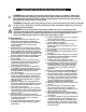
SIGHT AND HOLD THIS LEVEL WITH A VERTICAL TREE ffl « ----------A POWER POLE _o o ------------------- A CORNER OF A BUILDING ® > ----------------------------- OR A FENCE POST c 5 a ® o a. o ** o c >» a £ 3 o >t ® t o « ® Q. O ® c E k » 4-> V ■o WARNING: Do not mow on inclines with a slope in excess of 15 degrees (a rise of approximately 2.5 feet every 10 A ® O) a a V) ® (0 3 1. 2. 3. 4. feet). A lawn utility vehicle could overturn and cause serious injury.
SETTING UP 1. Lower tile cutti ng deck to the lowest position by sliding the deck lift lever to the appropriate slot 1. Remove all screws and staples from the crate. indicated by the label. Refer to Figure 7 and 2. Holding sides of the crate firmly, lift top. of the crate description on page 9 for more details. up and set it aside. Avoid tire punctures. 2. Remove the thumb screw and flat washer attaching 3. Remove and discard plastic bag covering the unit.
Thumb Screw Rat Washer Grass Catcher Chute 1. Piace the cutting deck in the lowest position by sliding the deck lift lever to the appropriate slot. 2. Slide the elbow of the grass catcher chute through the vehicle frame and align the chute opening with the corresponding opening on the vehicle frame. See Figure 5. Deck Mulch Plug Figure 3 NOTE: The grass bag must be in positior), on the vehicle, for any kind of mowing operation, including mulching and side-discharge of grass clippings.
OPERATION Know Your Lawn Utility Vehicle The Lawn Utility Vehicle is meant to be used as both a riding lawn mower and a utility cart. Its grass collector can be easily removed to expose the utility bed. Compare the illustrations in Rgure 7 with your lawn utility vehicle to learn about the location and features of its various controls. dk WARNING: The operation of any riding mower can result in foreign objects being thrown into the operator’s eyes, causing severe eye damage.
(off) position when (1) starting the engine, (2) travelling in reverse, and (3) if the operator ieaves the seat. Shift Lever This lever is located on the left side of the fender and has three clearly marked positions: FORWARD (F), REVERSE (R) and NEUTRAL (N). Follow the label on the unit to place the shift lever in the position desired. Choke Control This is located in front of the seat frame. Pull the choke control outward to activate choke for starting engine; push it inward once the engine starts.
1. 2. Brake Switch: This switch is located under the brake pedal assembly. The engine will not start witiiout first depressing the brake pedal. This switch will also shut off the engine if the operator attempts to get off the unit without setting the parking brake. 3. NOTE: SynUietic oil meeting ILSAC GF-2, API certification and API service symbol with “SJ/CF Energy Conserving" or higher is an acceptable oil at all temperatures.
NOTE: Do not hold the key in the START position for • To move in reverse: Place blade control lever in • OFF position. Place shift lever in the (R) position, check that the area behind is clear and then siowly depress the drive pedal. To drive on slopes: Refer to Slope Gauge on page 6 to determine slopes or inclines where you can operate your unit safely. Do not operate the vehicle if the gauge indicates a steep incline. longer than ten seconds at a time.
4. • Remove grass catcher to expose the utility bed. See Figure 9. Follow instructions on page 7 for grass catcher removal. Exercise caution in driving the vehicle when hauling things on its utility bed. Replace the bag on to the mower. Hook the loose end of the bag retainer straps to the vehicle frame to secure the grass bag. Using as Miilcher NOTE: Total load capacity, including operator, should not exceed 400 lbs.
MAINTENANCE General Recommendation • • • • A Always observe safety rules when performing any maintenance. The warranty on this lawn utility vehicle does not cover items that have been subjected to operator abuse or negligence. To receive full value from the warranty, operator must maintain the equipment as instructed in this manual. We do not recommend the use of pressure washers or garden hose to clean your unit.
3. 4. Remove the 5/8" hex flange nut which holds the blade to the blade spindle and the spindle shaft. Remove blade from the spindle. See Figure 11. Maintaining Engine Changing Engine Oil 1. 2. 3. 4. 5. 6. Disconnect spark plug wire and ground against engine. Place the blade control lever in the disengaged (OFF) position and engage the parking brake. Remove cutting deck by removing the three hairpin clips and flat washers that hold the deck to the hanger links.
5. Engine Tune-Up Specifications Completely loosen the two screws that hold the cover of the air cleaner. Remove the entire air cleaner assembly from the base. Lift the cover off the air cleaner, ^e Figure 13. • Armature air gap 0.006 - 0.014 inches • Spark plug gap 0.020 inches • Intake 0.004 - 0.006 inch • Exhaust 0.009-0.011 inch Lubrication See Figure 15 for an illustration of the lube points described below. • • 6. 7. A To clean cartridge, gently tap pleated paper side on a flat surface.
2. 1. Set the parking brake and push the vehicle. If the rear wheels roll, adjust the brake following instructions on page 20. 2. Remove three screws holding the cup and battery holder to the frame of the unit. Remove red and black insulation caps from battery terminals. Tires àk WARNING: Never exceed meiximum limit of air pressure shown on sidewall of the tire. The recommended operating tire pressure is 20-22 psi for both sets of tires.
SERVICE & ADJUSTMENT 4. ák WARNING: Never attempt any adjustment while the engine is running, except where specified in the operator’s manual. 5. WARNING: For all other adjustments, disconnect the sparit plug wire(s) and ground against the engine first. Then proceed with the adjustment. 6. Adjusting Seat Position 7. The seat position on the lawn utility vehicle can be adjusted to maximize the operator’s convenience. 8.
4. Retighten jam nuts when proper tension is reached. Test the adjustment. Readjust if necessary. JfHn Nut The front wheels should toe-in 1/16-5/16 inch. Toadjust toe-in, follow these steps: Adjusting Speed Control Rod This adjusbnent is necessary when the vehicle cannot hold the full range of speeds, or shows belt drag (“creep”) when the drive pedal is released. 1. Using 9/16" wrench, remove the hex nut and lock washer holding ball joint to the steering segment. See Figure 22 .
Adjusting Brake Shift Lever WARNING: Do not adjust the brake while A engine is running. Be sure to block the wheels of the vehicle before attempting any adjustment on the brake cable. NOTE: Adjustments are done at the cable end; for adjustment of the calipers, see a Sears service center. IMPORTANT: The brake cable should be adjusted so that it has a bit of slack when the brake is released. The front cable bracket is mounted on the frame behind the pedal assembly.
8. disengaging completely. Fora proper working machine, use belts available from Sears. 1. 2. Follow Rgure 25 for routing of belts and pulleys. Periodically check to see if these belts are too loose or damaged through wear and tear. If so, replace with new belt. Replace with new belt making sure that the hardware is properly secured and the belts are on the inside of the belt keepers. Jack Spindle Replacement Check jack spindle whenever you replace upper deck drive belts.
2. Remove the upper drive belt first by working from the back of the unit. Roll the belt off the idler pulley first and then off the transmission pulley. Next roll it off the variable speed pulley. 3. Working from the side of the unit, pull the lower drive belt tension pulley to the right and roll the lower drive belt off this pulley. 4. Using a 9/16 socket, remove the bolt holding the engine pulley, and drop the pulley down.
OFF-SEASON STORAGE If the lawn utility vehicle is to be inoperative for a period longer than 30 days, follow the steps below for storage. Preparing for Storage 2. Battery 3. 1. Fully charge the battery with a 6 amp battery charger. NEVER store battery without a full charge. 4. NOTE: If a charger with 6 amp output is not availabie, a io wer output charger may be used for a longer period of time. Do not charge the battery at a rate higher than 6 amps as it can damage the battery and reduce its life.
TROUBLESHOOTING Remedial Action Possible Cause Trouble Engine fails to start 1. 2. 3. 4. 5. 6. 7. Blade control lever engaged. Parking brake not engaged. Spark plug wire{s) disconnected. Choke not activated Fuel tank empty, or stale fuel. Blocked fuel line. Faulty spark plug. 1.Disengage blade control lever 2. Engage parking brake. 3.Connect wire(s) to spark plug. 4. Pull out the CHOKE control 5. Fill tank with clean, fresh gasoline. 6. Clean fuel line or replace fuel fitter 7.
PARTS LIST Parts List for Craftsman Lawn Utility Vehicle Model 247.270250 1 For reference only NOTE: For painted parts, please refer to the list of color codes below. Please add the applicable color code, wher ever needed, to the part number to order a replacement part. For instance, if a part, numbered 700xxxx, is painted polo green, the part num ber to order would be 700-XXXX-0689.
Parts List for Craftsman Lawn Utility Vehicle Model 247.270250 Key No. 1. 2. 3. 4. 5. 6. 7. 8. 9. 10. 11. 12. 13. 14. 15. 16. 17. 18. 19. 20. 21. 22. 23. 24. 25. 26. 27. 28. 29. 30. 31. 32. 33. 34. 35. 36. 37. 38. 39. 40. 41. 42. 43. 44. 45. 46. 47. 48. 49. 50. 51. 52. Part No.
Parts List for Craftsman Lawn Utility Vehicle Model 247.270250 IMPORTANT: For a proper working machine, use Factory Approved Parts. V-BELTS are specially designed to engage and disengage safely. A substitute (non OEM) V-Belt can be dangerous by not disengaging compieteiy. NOTE: For painted parts, please refer to the list of color codes below. Please add the applicable color code, wherever needed, to the part number to order a replacement part.
Parts List for Craftsman Lawn Utility Vehicle Model 247.270250 Key No. Part No. Description Key No. Part No. Description 1. 618-04007 Transmission Assembly* 25. 736-0169 Lock Washer 3/8 2. 619-0011 Spindle Housing 26. 736-0219 Bell Washer .39 x 1.13 x .062 3. 683-0446 Idler Bracket Assembly 27. 736-0247 FlatWasher3/8x 1.25” 4. 683-0447 Idler Bracket Assembly 28. 736-0427 Bell Washer .567 x 1.125 x .06 5. 710-0191 Hex Bolt 3/8-24x1.25” 29. 736-3052 Flat Washer .406 x 1.
Parts List for Craftsman Lawn Utility Vehicie Model 247.270250 NOTE: For painted parts, please refer to the list of color codes below. Please add the applicable color code, wherever needed, to the part number to order a replacement part. For instance, if a part, numbered 700-xxxx, is painted polo green, the part number to order would be 700xxxx-0689.
Parts List for Craftsman Lawn Utility Vehicle Model 247.270250 Key No. 1. Part No. Description 757-04000 Seat Part No. Description 38. 710-1752 Special Screw Clevis Pin Key No. 2. 683-0575 Support Bracket Assembly LH 39. 711-1165 3. 683-0576 Support Bracket Assembly RH 40. 712-0185 Speed Nut 1/4-20 * Hex Nut 4. 710-0604A TT Screw 5/16-18 X 0.625” 42. 712-0640 5. 710-1250 Carriage Bolt 5/16 x 1.5” 43. 712-0692 Hex Lock Nut Flange Lock Nut 6. 710-1681 HexBoltM8-1.25;20 44.
Parts List for Craftsman Lawn Utility Vehicle Model 247.270250 NOTE: For painted parts, please refer to the list of color codes below. Please add the applicable color code, wherever needed, to the part number to order a replacement part. For instance, if a part, num bered 700-xxxx, Is painted polo green, the part number to order would be 700-xxxx-0689.
Parts List for Craftsman Lawn Utility Vehicle Model 247.270250 Part No. Description 1. 683-0441 Shift Assembly: Front Lift 2, 683-0442 Pivot Bracket Assembly 3. 683-0448 Bracket Assembly: Lift Handle Key No. Part No. Description 25. 783-1082 Deck 26. 710-0347 Hex Screw 3/8-16x1.75 27. 710-0514 Hex Bolt 3/8-16 X 1.0 Key No. 4. 710-0641 Hex Bolt 1/4-20x2.25 28, 710-0650 TT Screw 5/16-18 x 0.875 5. 710-1681 HexBoltM8-1.25:20 30. 712-0417A Flange Nut 5/8-18 6.
Craftsman Lawn Utility Vehicle Model 247.27Q250 Key No, Part No. 649-0126 1. 2. 664-0107 Description Tube Assembly: Front Frame Grass Catcher Bag 3. 710-1194 Mach. Screw #10-24x1.0 4. 712-0161 Lock Nut #10-24 5. 723-0383 Retainer Strap 6. 736-0400 Flat Washer 7. 749-1260 Side Tube: Frame 8. 749-1262 Bag Handle 9. 749-1269 Support Tube NOTE: For painted parts, please refer to the list of color codes below.
Parts List for Craftsman Lawn Utility Vehicle Model 247.270250 |o w lii 1\ & 1 1■ xy 7 --------N ^ Key No. Part No. 611-0011 1. Description Shaft Assembly: Detent 2. 618-0072B Upper Housing Assembly 3. 618-0135 Drive Shaft Assembly: LH Brake 4. 618-04009 Axle Assembly 5. 661-0043 Brake Assembly: Yoke LH 6. 710-1325 TT Screw 1/4-20x1.625” 7. 717-0678 Break Pad 8. 719-0313B Lower Housing 9. 732-0863 Spring Detent 10. 737-0148 Grease 11. 741-0862 Ball: Detent: .250 12.
ENGINE MODULE
-0 Vi 0> ■4i o 0 1 3 fi) 3 f 3 < J 0 ro o 01 KEY SWITCH
Parts List for Craftsman Lawn Utility Vehicle Model 247.270250 Safety & Decorative Labels (MODEL PLATE ON RIGHT SIDE) 777D06242 ON STEERING CAP 777122019 777I20889 777I22020 777D06240 777I20890 777D06241 CRRFTSMRN 777530018, 777D06238 Some of №ese symbols will be found on the engine or in №e manual or labels on the lawn utility vehicle. Interpret them as indicated here, and follow the message.
Parts List for Briggs & Stratton Engine 12607-O324 for Lawn Utility Vehicle Model 247.
Parts List for Briggs & Stratton Engine 12607-0324 for Lawn Utility Vehicle Model 247.
Parts List for Briggs & Stratton Engine 12607-0324 for Lawn Utility Vehicle Model 247.
Parts List for Briggs & Stratton Engine 12607-0324 for Lawn Utility Vehicle Model 247.270250 Key No. 1 2 3 4 5 7 8 9 10 11 12 13 15 16 20 22 23 24 25 26 27 28 29 32 32A 33 34 35 36 40 43 45 46 51 51A 73 95 97 104 108 109 117 Part No.
Parts List for Briggs & Stratton Engine 12607-0324 for Lawn Utility Vehicle Model 247.270250 Key No. Part No.
INDICE índice de materias Página índice de materias Información sobre la garantía................ .....42 Prácticas de funcionamiento seguras . .....43 Determinación de la pendiente............... .....46 Montaje..................................................... .....47 Página Mantenimiento...................................... ...... 54 Servicio y ajustes................................. ......58 Almacenamiento prolongado.............. ...... 62 Resolución de problemas................... ......
PRÁCTICAS IMPORTANTES PARA UN FUNCIONAMIENTO SEGURO ák ák ák ADVERTENCIA: La presencia de este símbolo indica que se trata de instrucciones importantes de seguridad que debe respetar para evitar poner en riesgo su seguridad personal y / o material y de otras personas. Lea y siga todas las instrucciones contenidas en este manual antes de intentar poner esta máquina en funcionamiento. De no hacerlo puede ocasionar lesiones.
5. manejar bajo las ramas de los árboles, cableado, las aperturas de puertas, etc. cuando el operador pueda ser golpeado o sacado de la unidad, lo que resultarfa en lesiones personales de gravedad. Desenganche todos los embragues de ios accesorios, presione completamente el pedal de freno y cambie a 6. neutral antes de Intentar arrancar el motor. Su máquina está diseñada para cortar césped residencial normal de un alto rro mayor a 10".
Retire la llave сиагкк) deje la máquina sin atención p^u'a prevenir el uso no autorizado. 2. 3. Nunca permita que niños menores de 14 años operen esta máquina. Los niños de 14 años y más deben leer y comprender las instrucciones de operación y las reglas de seguridad contenidas en este manual y deben ser capacitados y supervisados por uno de los padres. 4. Servicio Manejo seguro de la gasolina 1. 5. Para evitar lesiones o daños sea sumamente cuidadoso al manipular la gasolina.
o z lU o (O < oc o lU VEA Y SOSTENGA ESTE NIVEL CON UN ÁRBOL VERTICAL co ----------UN POSTE DE ELECTRICIDAD < ---------------------LA ESQUINA DE UN EDIFICIO -------------------------------- O UNA VALLA ^4úa tD 't o a. < ( (O lU UJ (O 3 OC U O < X '■< X o o o. 1. 2, 3. 4. ADVEFfTENCIA; No pode en inclinaciones con pendientes mayores a 15 grados (una elevación de aproximadamente 2-1/2 pies por cada 10 pies). Un vehículo utilitario cortacésped puede volcarse y causar lesiones graves.
MONTAJE Desempaque la Unidad Tolva De Descarga Lateral 1. Se incluyen como piezas separadas una tolva de descarga lateral y un adaptador para forraje. Siga tas instrucciones para ensamblar la tolva de descarga. 1. Baje la cubierta de la cortadora a la posición más baja. 2. Retire el tornillo de mano, la arandela plana y la tuerca que unen ambos extremos de la tolva del recolector de pasto con la cubierta.
NOTA: La bolsa para pasto debe estar colocada en su posición en el vehículo utílitarío cortacésped, para cualquier operación de poda, incluyendo el forraje y la descarga lateral de recorte de pasto. Torpillo de mano Tolva del recolector de pasto Coloque la cubierta de la cortadora en la posición más baja deslizando la palanca de la cubierta hasta la ranura apropiada.
FUNCIONAMIENTO Características generales del vehículo utilitario cortacésped El vehículo utilitario cortacésped está diseñado para ser usado como una cortadora en la que puede montarse y un carro de servicio. Su recolector de pasto puede retirarse fácilmente para revelar la plataforma de servicios. Compare las ilustraciones en Figura 7 con su vehículo utilitario cortacésped para conocer más acerca de la ubicación y características de los diversos controles del vehículo.
Palanca de cambios en posición desenganchada (APAGADO) mientras (1)se arranca el motor, (2) está viajando en reversa y (3) el operador deja su asiento. Esta palanca se localiza al lado izquierdo de la defensa y tiene tres posiciones claramente señaladas: DE FRENTE (F), REVERSA (R) y NEUTRAL (N). Siga las instrucciones en la etiqueta en la unidad para colocar la palanca de cambios en la posición deseada.
Interruptor de control de cuchillas: Este interruptor está localizado en la columna de dirección. Si el operador intenta arrancar el motor, bajarse del asiento o retirar la bolsa para pasto con la palanca de control de cuchillas activa, se apagará el motor. Interruptor de bolsa para pasto: Este interruptor se localiza en el cabezal detrás del motor y forma parte del mecanismo de seguridad.
6. Gire la llave de encendido en sentido de las agujas del reloj hasta la posición ARRANQUE. Después de que arranque el motor, suelte la llave. Regresará a la posición de MARCHA automáticamente. ák NOTA; No sostenga la llave en la posición cíe ARRANQUE por más de diez segundos. Si lo hace puede causar daño al encendido eléctrico del motor de su vehículo . 7. ADVERTENCIA: Evite arrancar súbitamente, (as altas velocidades y las paradas repentinas.
Рага vaciar el recolector de pasto 1. 2. 3. 4. • Detenga por completo el cortacésped, coloque el freno de mano y saque la llave del encendido. Salga del asiento. Desenganche las correas de la bolsa del marco de la cortadora. Tire la bolsa recolectora de pasto por las dos manijas y llévela hasta el sitio apropiado de desecho. Aleje la bolsa de su cuerpo mientras la vacía. Vuelva a colocar la bolsa en la cortadora.
MANTENIMIENTO Recomendaciones generales ák • Siempre obedezca las reglas de seguridad cuando esté realizando cualquier trabajo de mantenimiento. • La garantía en este vehículo utilitario cortacésped no cubre artículos que hayan estado sujetos al abuso o negligencia del operador. Para recibir el valor completo de su garantía, e! operador deberá mantener el equipo de acuerdo con lo indicado en este manual. • • No recomendamos el uso de limpiadores a presión o mangueras de jardín para limpiarse unidad.
3. 4. Retire ia tuerca de brida hexagonal de 5/8" que sostiene la cuchilla al vástago y al eje. Retire la cuchilla del vástago. Vea Figuran. Mantenimiento del motor Cambio de aceite del motor 1. 2. 3. 4. 5. 6. Desconecte el cable de la bujía y póngalo de manera que haga masa contra el motor. Coloque la palanca de control de las cuchillas en posición de desenganche (APAGADO) y coloque el freno de mano.
5. Especificaciones para afinación Afloje k>s dos tornillos que sujetan la cubierta del filtro de aire. Retire el ensamble completo del filtro de aire desde la base. Levante la cubierta para sacarla del filtro de aire. Vea Figura 13. • Espacio de aíre del 0.006 - 0.014 pulgadas inducido • Espacio de la bujía 0.020 pulgadas de encendido Toma de entrada 0.004 - 0.006 pulgadas Emisión 0.009 - 0.011 pulgadas Lubricación 6. 7.
2. Coloque el freno de mano y empuje el veh (culo. Si los neumáticos traseros ruedan, ajuste los frenos siguiendo las instrucciones en la página 60. Acumulador eléctrico Cidiierta Neumáticos ák ADVERTENCIA; Nunca exceda la presión máxima de inflado de los neumáticos que se muestra en la pared lateral del neumático. La presión de operación recomendada para los neumáticos es de 20-22 psi para ambos juegos de neumáticos.
SERVICIO Y AJUSTES 4. Ajustes A ADVERTENCIA: Nunca intente hacer ajustes mientras la máquina está en funcionamiento, excepto que esté específicamente recomendado en el manual del operador. 5. ADVERTENCIA: Para otros ajustes, desconecte el cable(s) de la bujía de encendido y conéctelos a tierra con el motor. Luego proceda a realizar tos ajustes. 6. 7. Posición del asiento 8. La posición del asiento en el vehículo utilitario cortacésped se puede ajustar para mayor conveniencia del operador. 1.
4. V uelva a apretar las contratuercas cuando tenga la tensión apropiada. Pruebe el ajuste. Vuelva a ajustar en caso necesario. Alineación de las ruedas Figura 19 Las ruedas delanteras deben tener una convergencia de 1/16 -5/16 pulgadas. Para ajustar la convergencia, siga estos pasos; 1. Usando una llave de 9/16", retire la tuerca hexagonal y la arandela de cierre que sostiene la junta esférica al segmento de dirección. Vea Figura 22.
y sujétela con la arandela y la horquilla que quitó anteriormente. 7. Mueva la barra de cambio a (N) y controle que el ajuste sea correcto. Freno ák ADVERTENCIA: No ajuste el freno mientras el motor está en marcha. Asegúrese de bloquear las ruedas para que el vehículo no pueda moverse antes de realizar cualquier ajuste en el cable de frenos. Palanca de cambios NOTA: Los ajustss se hacen por el extremo del cable. Para ajustar los calibradores, acuda a un centro de servicio autorizado.
4. uso de herramientas especiales. Lea todo el siguiente procedimiento y detemnine si puede realizarlo completamente antes de intentarlo, en caso contrario contacte al centro de servicio Sears. 5. IMPORTANTE: Las carreas V que se encuentran en su vehículo utilitario cortacésped están especialmente diseñadas para engancharse y desengancharse con seguridad. Una correa V sustítuta (no- OEM) puede resultar peligrosa si no se desengancha completamente.
Trabajando рог debajo del vehículo, vuelva a instalar la polea del vástago de conexión con el perno que retiró anteriormente, 10. Levante la plataforma de servicios de regreso en su posición de operación, vuelva a unir el recolector de pastos si se requiere y vuelva a conectar el cable de la bujía de encendido. la polea de velocidad variable y la polea de transmisión. Reemplace las correas superiores de la cubierta siguiendo las instrucciones anteriores. Reemplace la correa de propulsión.
Salvando el equipo b. Si el tanque contiene únicamente gasolina, haga funcionar el motor hasta que se agote el combustible. c. Si agrega un aditivo a la gasolina en el tanque, haga funcionar el motor durante varios minutos después de agregarlo para que el aditivo circule por el carburador. Refiérase a la página 51 para obtener detalles sobre aditivos. Mientras el motor todavía está tibio, cambie el aceite. Consuite las instrucciones en la página 55. Retire la bujía y vacíe aproximadamente 0,5 oz o 15 mi.
Get it fixed, at your home or ours! For repair of major brand appliances in your own home. no matter who made it, no matter who sold it! 1-800-4-MY-HOME'* (1-800-469-4663) www.sears.com Anytime, day or night (U.SA and Canada) www.sears.ca For repair of cany-in products like vacuums, lawn equipment, and electronics, call for the location of your nearest Sears Parts and Repair Center. 1-800-488-1222 Anytime, day or night (U.S.A. only) www.sears.