f Save This Manual-" For Future Reference _ owner's manual MODEL NO. 113.196120 SAW ON LY or 113.196320 SAW WITH LEGS or 113.196420 CONTRACTOR'S SAW k_ Serial Number Model and serial numbers may be found at the front of the base. You should record both model and serial number in a safe place for future use. FOR YOUR SAFETY: READALL INSTRUCTIONS CAREFULLY 113:196420 __ARS / r.RRFT$M RN 10-INCH RADIAL SAW • assembly • operating • repair parts J Sold by SEARS, ROEBUCK AND CO., Chicago, Part No.
Fable of Contents Section Title ................................................................................ Page Safety ........................................................................................................................ 3 Introduction ............................................................................................................ 12 Assembly ................................................................................................................
Safety This manual has safety information and instructions to help users eliminate or reduce the risk of accidents and injuries, including: 1. Severe cuts, and loss of fingers or other body parts due to contact with the blade. 2. Eye impact injuries, and blindness, from being hit by a thrown workpiece, workpiece chips or pieces of blade. 3. Bodily impact injuries, broken bones, and internal organ damage from being hit by a thrown work_iece 4.
Safety Kickback Hazard Kickback is the uncontrolled propelling of the workpiece back toward the user during ripping. WARNING The cause of kickback is the binding or pinching of the blade in the workpiece. Several conditions can cause the blade to bind or pinch. KICKBACK II1_ When a workpiece kicks back, it could hit hard enough to cause internal organ injury, broken bones, or death. Read and follow the information instructions and under ripping safety.
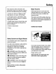
Safety Guard Function and Features The guard is a very important safety feature, designed to reduce the risk of injury associated with blade contact. Install the guard correctly. Follow the specific instructions in the ripping and crosscutting sections to set and use the guard correctly for each type of cuL Guard Features Include: 1.
Safety the pawls/riving knife knob. When lowered for crosscutting, it acts as a barrier to the leading edge of the blade. 6. Set of pawls to be lowered to the workpiece surface for ripping. They allow the workpiece to pass freely from infeed to outfeed side, but help stop the kickback motion from outfeed to infeed side by grabbing into the workpiece surface. Pawls must be re-set each time a different thickness workpiece is Guard Tab cut. 7.
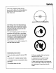
Safety Safety Instructions Read and follow all safety instructions. Personal Safety Instructions 1. Wear safety goggles labeled"ANSI Z87.1" on the package. It means the goggles meet impact standards set by the American National Standards Institute. Regular eyeglasses are not safety goggles. safety Goggles 2. Wear close fitting clothes, short sleeved shirts, and non-slip shoes. Tie up long hair. Do not wear gloves, ties, jewelry, loose clothing, or long sleeves.
Safety Saw Safety Instructions 1. Use guard, pawls and riving knife according to instructions. Keep them in working order. 6. Before turning on saw, clear table of all objects except workpiece to be cut and necessary fixtures, clamps, or feather-boards. 2. Routinely check saw for broken or damaged parts. Repair or replace damaged parts before using saw. Check new or repaired parts for alignment, binding, and correct installation. 7.
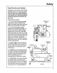
Safety 3. Rip only workpieces longer than the diameter of the blade. Do not rip workpieces that are shorter than the diameter of the blade being used. 4. Workpieces that extend beyond the saw table can shift, twist, rise up from the table, or fall as they are cut or afterwards. Support workpiece with table extensions the same height as the saw table. 5. To prevent tipping, support outer ends of extensions with sturdy legs or an outrigger. 6.
Safety On-Product Safety Labels There are several safety labels on the saw. They alert the user to hazards explained in the manual and remind the user how to avoid the hazard. Note where they are located on the saw. Read and follow the safety information and instructions in these labels. Refer to the manual for detailed explanations and instructions. At the outfeed side, to the right of the guard near the saw handle is this safety label to alert you to wrong way feed: INJUh;O0 \ NOTFEED \ MATERIALINTO\
Safety Near the saw handle is this safety label to alert you to thrown objects and to remind you to wear safety goggles: kWARNING On the clear plastic guard is this OSHA required label: TO AVOID INJURY SHUT OFF POWER BEFORE CLEANING A l= WARNING: JAMMED LOWER GUARD ]=J DANGER On the bottom surface of the motor, visible when the cutting tool is horizontal, is this safety label alerting you to use a guard when edge molding, and to position the cutting tool behind the fence: (see Accessories Section) Saf
Assembly Introduction In order to get the most enjoyment out of your radial saw it is important that the machine by properly assembled, adjusted, and aligned. This procedure, although not difficult, takes time; perhaps eight hours or longer for the inexperienced user. However, after this initial set-up a weekly trine-up can be completed in approximately ten minutes by checking the alignment and only adjusting those settings which are incorrect.
Assembly All models include: @ 5/16" - 18 x 3/4" long square head screw (4) 5/16" diam. hex nut (4) 1/4" diam.
Assembly crank Model 113.196320 cap and 113.196420 Only © 1/4" diam.x 5/8" long trusshead screw (40) (56 for contractor) Q leveling foot (4) 1/4" external tooth lockwasher (40 for 113.196320) (56 for 113.196420) 5/16" diam. external lockwasher (4) 3/8" diam. hex nut (8) 5/16"diam. 11/32" x 11/16" x 1/16" washer (8) hexnut (4) © 1/4" diam. hex nut (40 for 113.196320) (56 for 113.196420) Tools needed for Assembly ! i 5/16" diam.
Assembly ,_, WARNING For model 113.196420 Plugging in saw during assembly could result in electrical shock, or severe cuts from contact with spinning blade. Do not plug in saw at any time during assembly. Plug in saw only when it is to be used.
Assembly Mounting Saw 1. From among the loose parts, find the fob lowing hardware: 4 4 8 4 Hex Head Screws, 5/16-18 x 5/8 Lockwasher, 5/16 in. External Type Washers, 11/32 ID Hex Jam Nuts, 5/16-18 2. Place saw on legs so that holes in bottom of saw line up with holes marked X in top of legs. 3. Install screws, washers and nuts as shown. If you mount the saw on any other Craftsman base or flat bench, make sure Elevation Crank has proper clearance to rotate. The saw must be bolted down.
Assembly Attaching Carriage - Motor to Arm Remove carriage stop screw, lockwasher and tag. Read and understand warning tag before discarding. _I"_ _.. _Warning _Loc_sher .,_..__ _ Stop Screw _"-- Hex "L" Wrench (Supplied) Lock miter/arm lock before proceeding. Holding carriage assembly with both hands, carefully start and slide the carriage onto the tracks.
Assembly Remove saw blade. 1. Tighten carriage lock knob, located on right side of arm. 2. Loosen guard clamp screw approximately 4 turns. 3. Use one hand to lift the clear plastic guard at the front of the saw. Pull down to loosen "-- Blade 4. Use the other hand to grasp the rear of the guard (below the dust elbow). 5. Rotate the entire guard assembly forward approximately 45 °. 6. Remove the guard assembly. 7. Motor shaft has left hand threads.
Adjustments Arm Lock Adjusting Miter/Arm Lock Lever Wheel With the arm at an "unindexed" position and the miter lock applied, the locking action should feel tight and secure. Considerable effort should be required to move the arm back towards 0 °. Its is always possible to force the arm because of the leverage advantage the long ann provides. However, the arm should resist moving when a reasonable amount of force is applied. To check follow these steps: 1.
Adjustments Yoke Clamp Adjustment Yoke Lock Handle To check the yoke clamp adjustment follow these steps: 1. Pull the yoke lock handle towards the front of saw to unlock yoke. Pull forward on the swivel index pin (on the left side of carriage) to disengage index pin. 2. Swivel the motor halfway between the crosscutting and rip position so the index pin is not engaged. 3. Lock the yoke lock handle. 4. Grasp the motor with both hands and try to swivel it back into the crosscut position. It should not move.
Adjustments Bevel Lock Lever 0 The purpose of the bevel lock lever is to lock the motor at any angle. To check follow these steps: Bevel 1. Unlock the bevel lock lever. Move the, Pin bevel index pin to the left and rotate the saw to approximately 30 °. Lock the bevel lock lever. 2. Use both hands as shown and try to force the motor out of position. If the motor moves, the bevel lock lever needs to be tightened.
Adjustments Arm to Column Adjustment If you can move the end of the radial ann up and down when the ann is unlocked, adjust as directed below: 3/8-16 Bolts a. Remove two (2) screws from rear cover plate. Tighten evenly top two 3/8-16 bolts until arm moves fn-mly. There should be no vertical or horizontal movement in the arm when miter/arm lock is locked and unlocked. b. Bottom two nuts should be snugged evenly, but not nearly as tight as top two bolts. c.
Adjustments 2. Loosen (2) 1/4 - 20 Gib socket cap screws on the left side at the rear of the column support slightly (1/2 turn). Hex "L" Wrench ,j_ T"-_ I ] I 3. Elevate, and then lower the Arm: a. If the column tube binds and elevation is difficult, loosen two 5/16 - 18 plated bolts on front side of the column support until you achieve smooth but firm elevation. Front Bright Plated ° I- b.
Adjustments Adjusting Carriage Bearings If the carriage bearings are loose it not only allows the saw blade to move up, down, and sideways but also results in inaccurate cuts. Before following these steps make sure the tracks (steel rods) and carriage bearings have been cleaned by wiping them with a clean cloth.
Adjustments Positioning Table Supports/Installing Front Table/Leveling Front Table Note: The goal in adjusting the table supports and leveling the front table is to make sure that the table is the same distance from the radial arm at all points. This ensures that when the table and blade are installed the clearance between them will be equal at all points. Positioning Table Supports 1. Release bevel lock lever, move bevel index lever to the left and rotate the motor to position arbor shaft down.
Adjustments Installing Front Table l. Set out: - front table - tee nut - 1/4" U-clip - 1/4" diam. x 7/8" long cup point set screw - four 1/4" diam x 1" long pan head screws - 1/4" diam. x 1-3/4" long pan head screw - five 17/64" I.D. x 5/8" O.D. fiat washers - four 1/4" lock washers - four 1/4" diam. hex nuts. 2. Identify top and bottom of table: top has counterbored holes. Place table bottom side up on solid surface. Hammer tee nut into leveling hole. (This hole is not cotmter-bored from the top). 3.
Adjustments 5. Drop a fiat washer into each counterbored hole. 1/4-20 x 1-3/4" Pan Head Screw 17/64" Flat Washer 6. Start 1-3/4" long pan head screw through center hole and into U-clip, but do not fully 1/4-20 x 1" Pan Head Screw _Front Table tighten. 7. Start cup point set screw through leveling hole and into tee nut, but do not fully tighten. ...--- Lockwasher Hex Nut 8. Put 1" long pan head screw in each of four remaining holes and through matching holes in table supports.
Ali nment This section applies to all three models covered by this manual. The saw and blade must be aligned correctly for two reasons: 1) to prevent binding of the blade and workpiece, which can cause jams, kickbacks, or thrown worklSieces; 2) to make accurate cuts. _WARNING Plugging in saw during alignment could result in accidental start-up and severe cuts from contact with spinning blade. Do not plug in saw at anytime during alignment or adjustment. Plug in saw only when it is to be used.
Alignment Miter/Arm Lock Lever 3. Lower ann until saw blade just clears the front table. Lock the yoke lock handle and bevel lock lever. 4. Place a framing square on the table, as shown, with one leg of square firmly against rear edge of front table. Position the blade and square until the leg of the square just contacts a tooth of the blade. Mark this tooth. 5. When the carriage is moved slowly back and forth on the arm, the marked tooth should just touch the square at all points.
Alignment Install Table Clamps 1. Insert fence, then spacer table, then rear table. Front Table Fence Spacer Table Rear Table / \ I /-- 2. Set out two unassembled table clamps: - two cup washers - two clamp brackets - two square nuts - two thumbscrews 3. Slip square nut into slot at top of clamp bracket. 4. Insert thumbscrew through rear opening, and turn clockwise until it comes out other Square Nut Cup Washer side about 1/2". Note: Ifyouput screw in front opening, clamp will not work.
Alignment Square Blade to Table for Crosscutting Bevel Indicator The goal of this adjustment is to make the blade square to the table so that crosscuts will be accurate; otherwise all crosscuts will have a slight bevel angle. 1. Lower blade until it just clears front table. Lock bevel, miter, rip, and yoke locks. 2. Place a framing square on the table with the short leg against the saw blade and long leg parallel to fence.
Alignment Square Blade to Fence Left Hand Carriage Cover The goal in setting the blade square to the fence is to reduce the risk of kickback when ripping. This adjustment will also reduce splintering of the workpiece and burning of the kerf during ripping and crosscutting. I Rip Fence 1. Lower blade until it just clears table. 2. Unlock rip lock, Pull blade forward to front of ann. Lock rip lock. 3.
Alignment Make Blade Parallel to Table The goal of this adjustment workpiece from being This adjustment 1. Lock ripping and burning the or damaged. oo::: l splintering of the keff and crosscutting. arm in straight 2. Pull blade thrown will also reduce of the workpiece during is to keep forward crosscut position. and lock rip lock. 3. Raise blade at least 2" above table. 4. Lock motor at 90 ° bevel (blade horizon- Correct tal). 5.
Alignment Installing and Adjusting Indicators. Rip Scale Screw #6-32 x 1/2 Note: The rip scales and pointers are intended to be used for quick settings. For greater accuracy, take direct measurement between blade and fence. 1. Pre-assemble indicator and twin nut. Loosen but do not remove two screws which attach left hand carriage cover. 2. Tilt carriage cover and install rip indicator with twin nut on inside of cover. Tighten carriage cover attaching screws. Twin Nut 3.
Alignment 6. The blade "Out-Rip" scale indicator on left hand side of the radial arm is adjusted in essentially the same manner as blade "InRip" indicator, except position blade with 2 inches between fence and face of saw blade. 1 The tip-scale indicator should be positioned to read 2 inches on upper portion of the blade "Out-Rip" scale. Note: With saw blade and fence in the position shown, the upper portion of the blade "Out-Rip" scale is used.
Alignment Align Riving Knife to Blade The goal of this adjustment is to position the riving knife directly in line with the blade. Riving knife alignment is an important safety factor. The riving knife rides in the kerr of the cut workpiece during ripping to keep the two sides of the workpiece from pinching on the blade. Blade pinching is a cause of kickback. Pawls Fence Riving Knife Correct 1. Lock yoke in in-rip position (blade towards colum, motor towards front of arm). 2.
Controls Bevellndex Lever Miter/Arm Lock Lever On-Off Switch Yellow Key Miter/Arm Lock Function OpemtionlComments Frees radial arm to move; locks in any desired position; pre-set indexed positions at 0°, 45°L, 45°R Pull lever forward to release index then swing arm left or right Hold in unlocked position moving arm while On-Off Switch Turns motor on/off Pull on, push off Requires yellow key Yellow Key Allows saw to be switched on Insert into on-off switch Remove after turning saw off Bev
Controls Yoke Index Lever Table Clamp Bevel Lock Lever Elevation Crank \ Con_ol _uncfion Ope_rafiqn/Comments Bevel Lock Lever Frees motor to rotate; locks in any desired position t_ll lever to release and push to lock Support motor before unlocking because it can swing down quickly Bevel index lever must be unindexed before moving motor Elevation 38 Crank Raises/lowers radial arm Turn clockwise to raise, counterclockwise to lower Table Clamp Frees table sections to allow changing fence po
Controls Rip Scale & ) Indicator Rip Lock e Lock Handle Saw Handle Bevel Lock Lever tonal Function Operation/Comments Yoke Lock Handle Locks yoke in rip or crosscut position Pull handle forward to release; push handle reward to tighten Yoke index lever must be unindexed before rotating yoke Rip lock Locks carriage to radial ann for tipping Rotate counterclockwise to release carriage; turn clockwise to lock carriage in position Lock before ripping Rip Scale & Rip Indicators Tells approximat
Controls Guard Clamp Screw Guard Pawls/Riving Knife Knob Hold Down Knob Riving Knife Bracket Riving Knife Pawls Hold Down 4O Con_ol Function Operation/Comments Guard Clamp Screw Secures guard to motor, frees guard for removal Tum counterclockwise to loosen, clockwise to tighten Guard Protects against contact with upper blade; partially protects against contact with lower blade; acts as sawdust deflector Upper part remains fixed in level position.
Controls Pawls/Riving Knife Knob Tab Pawls \ Riving Knife Fu_on Operation/Comments Guard Tab Provides manual way to raise clear plastic guard during tipping when workpiece fails to raise it Push and hold until workpiece clears guard, then release Pawls/Riving Knife Knob Frees pawls and riving knife to independently move up and down Turn counterclockwise Pawls During ripping, slow or stop kickback by digging into workpiece; when lowered during crosscutting, provide partial barrier to leading edg
Electrical Connections Motor Specifications _WARNING The AC motor used on this saw is a capacitor-start, non-reversible type. The models covered in this manual have the following specifications: If not properly grounded, this power tool could cause electrical shock, particularly when used in damp locations. Specification: _WARNING Model 113.196120 Model 113.196320 Model 113.196420 Rated H_P. 1.5 1.5 1.5 Max Developed HJ _. 2.5 2.75 3.
Electrical Connections Grounding Lug WARNING To maintain proper tool grounding, if outlet you are planning to use for this power tool is a 2-prong type do not remove or alter grounding prong in any manner. An adapter is available for connecting the plug to 2-prong receptacles. The green grounding lead or grounding lug extending from the adapter must be connected to a permanent ground such as to a properly grounded outlet box. Extension 3-Prong / _ Make Sure This Is 2-Prong ,_WARNING .eco.
Electrical Connections Dual Voltage Motors Models 113.196320 and 113.196429 ONLY! To Change Motor Voltage to 240 A.C. Under normal home workshop conditions, if full voltage is supplied to the motor, your saw will operate efficiently on 120V.
Crosscuttin Slraighl Crosscutting Bevel Miter Defined Compound Crosscutting is cutting a workpiece to length. The workpiece is held firmly against the fence, and the blade is pulled through the workpiece to make the cut. Straight, bevel, miter, and compound cuts can be made. Rolling Carriage Crosscutting WARNING Satety The hazards associated with crosscutting include: exposed blade teeth, rolling carriage, and thrown workpiece.
Crosscutting Crosscut Kerfs A kerf or shallow cut is needed and fence to serve as a path for to ensure that the blade cuts all through the workpiece. A kerf each different cutting path. in the table the blade and the way is needed for To make an approximately 1/16" deep kerr: 1. Prepare table: - put fence in font position - tighten table clamps 2.
Crosscutting Making Crosscuts Follow these steps to make crosscuts. 1. Prepare table: - put fence in front position - tighten table clamps 2. Prepare blade: - lock blade in crosscut position - lock radial arm at desired miter angle - lock motor at desired bevel angle* - unlock rip lock and push blade to rearmost position, behind fence - lower blade into kerr* but not touching keff bottom (blade should move freely).
Crosscutting Repetitive Crosscutting Repetitive crosscutting is the repeated and continuous cutting of many pieces of lumber to the same length. Carriage and length stops can help make this type of crosscutting more efficient. Carriage Stop A carriage stop defines the distance needed to pull the blade through to complete each cut. This will prevent pulling the blade through more than the recommended distance. Length Stop To make a carriage stop use lx2 lumber:.
Ripping Ripping Defined Ripping is changing the width of a workpiece by cutting along its length. The workpiece is fed into the blade, which rotates in a fLxed position, parallel to the fence and a set distance from the fence. A solid fence (no kerfs) serves as a guide for the workpiece. Place the fence in the front position for narrower workpieces, or in the rear position for wider ones.
Ripping Workpiece Positioning Always set up so that the wider part of the workpiece is between the blade and fence. This gives you greater clearance for push sticks, and allows better stability for feeding the workpiece. Example: To rip 2" off a 10" wide board, set blade in in-rip position 8'" from rear fence. Push Sticks and Push Blocks Use push sticks and push blocks instead of the hands to push the workpiece through to complete cuts. They help keep hands away from the blade.
Ripping Outfeed Zone Hazard ,_DANGER Rotational force of blade can pull hands and fingers back into blade. Touching, holding, or pulling on outfeed side of workpiece while blade is still spinning will result in fingers, hand or arm being cut off. To reduce risk of outfeed hazard: DANGER _J Set pawls and riving knife; they act as partial barrier to outfeed side. _J Start and finish cut from infeed side. _J Keep both hands on infeed side. Keep hands away from ouffeed side.
Ripping To reduce risk of kickback: _/Set pawls and riving knife according to ripping set-up procedure. Correctly set riving knife is more likely to prevent work_iece from binding or pinching blade; correctly set pawls are more likely to grab into workpiece to stop or slow kickback if one happens. .4 Check that riving knife is in line with blade (see Aligtmaent: Riving Knife to Blade). Cut only straight workpieces so surface will lie flat on table and edge will stay tight against fence.
Ripping Hold Down Function The hold down must be set correctly during ripping to act as barrier against the infeed side of the blade, to help keep the workpiece flat on the table, and to deflect worlqaiece chips. It must be lowered to just clear the workpiece. The hold down must be re-set each time a different thickness workpiece Set Hold-Down to workpiece just clear ___ is cut. Follow the Ripping Set-Up Procedure to correctly set the hold down.
Ripping Ripping Set-up Procedure _IL WARNING Follow these steps before ripping. If workpiece is pushed along fence with kerfs, workpiece could get caught on kerf, pinch blade and cause kickback. Do not use cross- These steps must be repeated each time a different thickness workplece is ripped. A kerr must be made for each different cutting fence for ripping. width cuL Also see the special notes for bevel set-up that follow this section. 1.
Ripping 8. Remove workpiece from table. 9. Ready push stick or push block. 10. Set up table extension(s) and support their outer ends. Do not use another person to support workpieces because this can cause kickback and it exposes helper to potential hazards at outfeed side. Special Notes for Bevel Set-Up ,_CAUTION Bevel ripping creates unique problems of visibility and feeding. Before cutting, check the set-up using both in-rip and out-rip.
Ripping 2. Insert yellow key and turn saw on. 3. Stand at infeed side and out of line of workpiece, in case of kickback finish cut from infeed side. Start and 4. Put workpiece on table, in front of hold down, and tight against fence. To hold workpiece in position, put left hand on table, at least 8" in front of hold down, and lightly press fingers against workpiece. Support workpiece with table extension or right hand. CAUTION For large workpieces use a featherboard in place of your hand on the table.
Ripping Dado Blades, Molding Heads See Accessories for information on safety, installation and use of dado blades and molding heads. Edging Edging is the use of a dado blade or molding head in the horizontal position. It is an advanced technique that requires a molding head guard and a special fence. See Accessories for information on safety, installation and use of dado blades and molding heads for edging. See Cutting Aides for information on making the special fence. Ripping Hints 1.
Cutting Aides Molding/Sanding Instructions for operating the Molding Head are contained in a booklet furnished with the Rear Table Molding i/ head. For use of Molding Head Cutter or Drum Sander with saw arbor vertical, the rear table requires an opening (next to rear face of fence) for clearance. Cut this opening as shown. -lr 2-1/2" t Note: Spacer table is too narrow for this opening. Be sure opening is cut in the rear table.
Cutting Aides Cutting aides include push sticks, fences, auxiliary fences, push blocks, featherboards, and straight edges. Push SUcks Slightly Less Than Thickness Of 3/4 Workpiece To make a push stick, use 3/4" knot-free lumber, or a standard lx2. Cut to dimensions shown (inches). Up To 3/8" -T-- _X 112 1"5/8__.__ '_'--._ "_"4_o,otc. J--> .A 15 ._"_ l_.._ Fences Fences are required for all saw operations. To make a fence, use 3/4" knot-free l_mber cut to table length.
Cutting Aides Clamp the featherboard to the front table, so that the angled edge of the featherboard is against the workpiece on the infeed side of the blade. Do not clamp the featherboard against the cut off part (out-feed side) of the workpiece. If clamped to the outfeed side, the featherboard can squeeze the kerf dosed, put binding pressure on the blade, and cause kickback. Straight Edge for Irregular Workplece _WARNING If you try to rip an irregular workpiece, it could bind blade and cause kickback.
Accessories Accessories Safety Information 1. Use only accessories listed in this section. Use of any other accessory or attachment might increase the risk of injury to you or others. 1. Put inside loose collar on arbor shaft first, then install dado. Tighten blade nut directly against outside surface of dado. 2. Read and follow instructions that come with accessory. 3. Do not install accessories on both ends of arbor shaft at same time. for Dado 2. Saw arbor is designed for dado up to 13/16" wide.
Accessories Accessories for this Saw These accessories are designed to fit this saw. Read and follow instructions that come with accessory. Item .......................................... Catalog No. Auxiliary Table Cover ................................... see catalog Blades (10" with 5/8" hole) ........................... s_g catalog Dado Blades Adjustable Dado 7"-24 tooth carbide ................................... see catalog 7"-32 tooth carbide ...................................
Maintenance General Information When new, the saw requires no lubrication. The saw has been partially aligned and all bearings are lubricated and sealed for life. In time, in order to keep the saw in good working order, it will be necessary to dean, lubricate and m-align. Oil Here _WARNING TO avoid shock, burns, or lacerations from accidental start up of saw, turn power switch off and unplug saw before doing maintenance or servicing saw.
Maintenance Replacing Pawls Make sure the teeth of the pawls are always sharp. If they become dull the pawls must be replaced: 1. Use 7/16" wrench to remove Remove old pawls. hex nut. 2. Install new pawls. Place spacers exactly as shown. 3. Re-install hex nut. Blade Changing To change the saw blade: 1. Turn switch off, remove yellow key, and unplug saw. 2. Remove guard. 3. Use both blade wrenches in scissor action to loosen blade nut. Note: Arbor shaft has left-hand threads.
Troubleshooting HAVE YOU FOLLOWED ALL STEPS OF THE ALIGNMENT PROCEDURE? IF YOU HAVE NOT FOLLOWED THEM IN THEIR PROPER SEQUENCE, YOU CANNOT EXPECT ACCURATE CUTTING RESULTS. This Edge of Board Against Fence For All Cuts In addition to the proper alignment of your saw, you must also become familiar with the following practices in order to expect the best results. 1. Edge of workpiece which is placed against fence must be as straight as the long side of your framing square. 2.
Troubleshooting Motor Problem Possible Cause(s) What to Do Motor ove_hemsor stalls Ovecloadedpower Reduce line load by removing other fights, appliances Feedingrate too fag Slow down rate of feed ImlxoPcr motorcooling Vacuum sawdust from motor to allow normal air circulation Saw blade has heel Check alignment Saw blade is dull Sharpen blade Motor Overloaded Slow down rate of feed Need 15 amp circuit Call your electrician Need 15 amp slow-blow fuse Install correct fuses Low voltage Check
Troubleshooting Cutting Problem Possible Cause(s) What to Do Looselocks Chock miter, rip, bevel, and swivel locks.
Troubleshooting Cutting Problem Cause(s) What to Do Workpiece str_es riving knife during ripping Riving knife notin line with blade Alignrivingknifeto blade Workpiece binds, smokes, and motor slows or stops when ripping Saw blade out of alignment Re-align Warpedworkpiece Do not cut severely warped pieces Feed rote too fast Slow feed rate Carriage assembly loose Adjust carriage bearings, then realign saw Fence not straight l_place fence Dull or incorrect blade Sharpen or replace blade Saw
Notes 69
,,,,q o PARTS LIST FOR CRAFTSMAN 10" RADIAL SAW MODEL NUMBERS 113.196120; 113.19_20 & 113.
PARTS LIST FOR CRAFTSMAN 10" RADIAL SAW MODEL NUMBERS 113.196120; 113.196320 & 113.196420 Always order by Part Number - Not by Key Number FIGURE 1 Key No Part No. 1 2 3 63518 75090 60339 4 5 6 7 6O353 815649 63669 STD601105 8 63670 821361 63686 805494 436594 9 11 12 13 14 15 16 17 18 19 STD551131 9421620 20 21 821473-3 60337 22 23 24 STD512520 821367 STD551010 63884 63885 STD541110 De_xlptlon Cord, with Plug Cover, Rear Arm Screw, Hex Hd Locking, 3/8-16 x 2-1/8 High Strength Washer, .
"4 PARTS LIST FOR CRAFTSMAN 10" RADIAL SAW MODEL NUMBERS 113.196120; 113.196320 & 113.196420 20 :O 20 mll "10 37 3O \ 28 29 • Any attempt to repair this motor may create a HAZARD unless repair Is done by a qualified service technician. Repair service Is available at your nearest Sears Store.
PARTS LIST FOR CRAFTSMAN 10" RADIAL SAW MODEL NUMBERS 113.196120; 113.196320 & 113.196420 FIGURE Key No Part No. STD601105 2 3 4 5 6 7 8 9 10 11 12 13 14 63661 63786 S1D51 O605 120399 63657 63893 63658 63656 STD551 031 STD551231 STD523107 63778 63782 15 16 17 18 19 20 63777 STD541462 STD551052 30567 30530 60336 21 22 23 24 25 26 27 28 29 30 31 32 33 34 63779 63528 30521 63659 63660 63641 STD541231 30495 62498 9-32668 STD541411 STD551037 63652 63651 2- Description * Screw, Type "1" Pan Rec.
..,.j j_. ZI PARTS LIST FOR CRAFTSMAN 10" RADIAL SAW MODEL NUMBERS 113.196120; 113.196320 & 113.196420 (I) "ID m I_11 II "R 26 18 "0 27 19 28 ,27 15 144 13 31 32 33 34 I 8 9 47_@\\ \ \ \ 44 \ _ 28 46 45 44 43 FIGURE 3 35 36
O_ PARTS UST FOR CRAFTSMAN 10" RADIAL SAW MODEL NUMBERS 113.196120; 113.196320 & 113.
PARTS LIST FOR CRAFTSMAN 10" RADIAL SAW MODEL NUMBERS 113.196120; 113.196320 & 113.196420 Alwaysorder by Part Number.
Repair Parts PARTS LIST FOR CRAFTSMAN 10" RADIAL SAW MODEL NUMBERS 113.196120, 113.196320 & 113.196420 _- IF THIS PART IS REMOVED, DISCARD AND REPLACE WITH A NEW PUSH NUT. 22 FIGURE Key No Part No. 5 - ARM ASSEMBLY Description Key No Part No.
PARTS UST FOR CRAFTSMAN 10" RADIAL SAW MODEL NUMBERS 113.196120; 113.196320 & 113.196420 Always order by Part Number- Not by Key Number FIGURE- Key No Part No. 1 2 3 4 5 6 7 8 STD503705 63623 60330 63611 63610 STD572510 821346 9416187 9 10 11 12 13 14 15 16 17 STD523110 60078 STD541037 STD551137 6O340 STD523712 186648 817398-1 60367 18 60336 19 20 21 63609 821348 635OO 22 63614 Description * Screw, Soc.
Repair Parts PARTS LIST FOR CRAFTSMAN 10" RADIAL SAW MODEL NUMBERS 113.196320 & 113.196420 4 4 4 4 3 1 13 I FIGURE Key No Part No. Description 1 2 3 4 5 6 7 821343 60314 63751 63750 STD551225 STD541025 STD523106 Leg Screw, Truss Hd. 1/4-20 X 5/8 Stiffener, R.H. Stiffener, L.H. * Lockwasher, External 1/4 * Nut, Hex 1/4-20 * Screw, Hex Hd 5/16-18 x 5/8 6 - LEG SET Key No Part No.
f f owner's manual 10-1NGH SAW SERVICE Now that you have purchased your 1[]-Inch radial saw, should a need ever exist for repair parts or service, simply contact any Sears Service Center and most Sears, Roebuck and Co. stores. Be sure to provide all pertinent facts when you call or visit. MODEL NO. 113.196120 The model number of your 1D-inch radial saw will be found label attached to your saw, at the front of the base. on a SAW ONLY or 113.196320 SAW WITH LEGS or 113.