NetPassage WPE53G User Manual
Table of Contents OVERVIEW THE PRODUCT .............................................................. 1 Introduction ................................................................................................... 1 Features and Benefits................................................................................... 2 When to Use Which Mode........................................................................... 4 Access Point Mode.....................................................................
Access the TELNET Command Line Interface..................................... 66 Access the Secure Shell Host Command Line Interface .................. 67 Set the WEB Mode ...................................................................................... 68 Setup SNMP.................................................................................................. 69 Setup SNMP Trap......................................................................................... 70 Setup STP ....................
Setup Repeater......................................................................................... 127 SECURE YOUR WIRELESS LAN..................................................... 132 Setup WEP .................................................................................................. 133 Setup WPA-Personal ................................................................................. 134 Setup 802.1x/RADIUS for Access Point................................................... 136 Setup 802.
Overview the Product Introduction NetPassage WPE53G is a high-performance and low-cost IEEE802.11b/g Access Point using the latest AR5007 technology. NetPassage WPE53G is also very small compared to other Access Points in the market. Using Atheros System-on-Chip (SoC) solution, WPE53G supports high-speed data transmission of up to 54Mbps or 108 Mbps. Moreover, Power-over-Ethernet support enables NetPassage WPE53G to be used even in areas without readily-available power outlets.
Features and Benefits • Compact Form Factor Small in dimension; light in weight. You can bring it with you anywhere. • Multiple-SSID Supporting VLAN Segmentation. Up to 4 virtual access points (VAP) with unique BSSIDs is supported and if required, traffic from each VAP can be tagged to a specific VLAN and bridged. The security mode for each VLAN can be configured separately.
• Spanning Tree Protocol Provides redundancy and automatically reconfigures to changes in network topology. • Parallel Broadband In Gateway Mode, Load-Balancing and Fail-Over Redundancy provides scalable Internet bandwidth. • SNMP Trap SNMP traps logs and provides notification of significant events in the network. • Antenna Control and Alignment Allows the user to select the specific antenna to use, and also adjust it for optimal throughput.
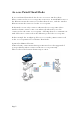
When to Use Which Mode Access Point Mode The Access Point Mode is the default mode of the access point and enables the bridging of wireless clients to access the wired network infrastructure and also enables their communication with each other. In this example the wireless users are able to access the file server connected to the switch, through the access point in Access Point Mode.
Access Point Client Mode In Access Point Client Mode the device acts as a wireless client. When connected to an access point, it creates a network link between the Ethernet network connected at this client device, and the wireless Ethernet network connected at the access point. In this mode it can only connect with another access point.
Wireless Routing Client Mode In Wireless Routing Client Mode the Ethernet port of the access point may be used to connect with other devices on the network while Internet access would be provided through wireless communication with a wireless ISP.
Gateway Mode In Gateway Mode, the access point supports several types of broadband connections in a wireless network after you have identified the type of broadband Internet access you are subscribed to.
Broadband Internet Access Type: Static IP Address Use Static IP Address if you have subscribed to a fixed IP address or to a range of fixed IP addresses from your ISP.
Wireless Adapter Mode In Wireless Adapter Mode, the access point can communicate wirelessly with another access point to perform transparent bridging between 2 networks, like in the Access Point Client Mode. In this mode, however, the wireless adapter connects to a single workstation only. No client software or drivers are required to use this mode. Optional additional feature: Point-to-Point connection in this operation mode is also supported if you specifically wish to connect with an access point only.
Transparent Client Mode In Transparent Client Mode, the access point provides connection with an access point* acting as the RootAP. This operation is designed for the implementation of Point-to-Point and Point-to-Multipoint connections. Point-to-Point An access point acts as Root AP and 1 other access point acts as Transparent Client. Point-to-MultiPoint An access point acts as Root AP and several other access point acts as Transparent Clients.
Difference Between other client modes and Transparent Client Mode Other client modes Transparent Client Mode Connectivity with any Connectivity with RootAPstandard APs. supported APs. All devices connected to Devices connected to the the Ethernet port use a Ethernet port flow through common MAC address for freely and transparently communications with the without the MAC address AP. restriction.
Repeater Mode The access point comes with a built-in Repeater Mode to extend the range, and substantially enhance the performance of the wireless network by allowing communications over much greater distances. In Repeater Mode, the access point acts as a relay for network signals on the network by regenerating the signals it receives, and retransmitting them to extend the range of the existing network infrastructure. Detailed information on the Repeater Mode is available in the Repeater Setup section.
Panel Views and Description Page 13
Install the Hardware Setup Requirements • • • CAT5/5e Networking Cable. At least 1 computer installed with a web browser and a wired or wireless network interface adapter. All network nodes installed with TCP/IP and properly configured IP address parameters. Using power adapter to supply power to the unit Step 1: Connect the external antenna to the SMA connector of the access point.
Step 2: Insert one end of the Ethernet cable to the Ethernet port on your access point, and the other end of the cable to your PC’s Ethernet network adapter. Step 3: Attach the power adapter to the main electrical supply, and connect the power plug into the socket of the access point. Step 4: Turn ON the power supply and power ON your PC. Notice that the LEDs: Power and Port 1 or 2 (depending on which port you have connected the RJ45 Ethernet cable to) have lighted up.
Using PoE to supply power to the unit PoE is fully compatible with your access point. This accessory supplies operational power to the wireless AP via the Ethernet cable connection. Users who wish to use it to supply power to the access point may follow the installation procedures as shown below: Step 1: Connect the external antenna to the SMA connector of the access point.
Step 3: Next, connect the RJ45 Ethernet cable attached to PoE to your PC’s Ethernet network adapter. Once you have finished configuring your access point, you can connect the PoE RJ45 Ethernet cable to your network device, such as to a switch or hub. Step 4: Connect the power adapter supplied with PoE to the main electrical supply and the power plug into the socket of PoE. Note: The voltage and current supplied to the access point’s power adapter and PoE power adapter are different.
Setup for Windows XP/2000 Step 1: Go to your desktop, right-click on the My Network Places icon and select Properties. Step 2: Right-click the network adapter icon and select Properties. Step 3: Highlight Internet Protocol (TCP/IP) and click on the Properties button. Step 4: Select the Use the following IP address radio button. Set the IP address to 192.168.168.X and subnet mask to 255.255.255.0, where X can be any number from 2 to 254.
Step 5: Click on the OK button to close all windows. Step 6: To verify that the IP address has been correctly assigned to your PC, go to the Start menu, Accessories, select Command Prompt, and type the command: ipconfig/all Your PC is now ready to communicate with your access point.
Access the Web Interface Access with uConfig The UConfig utility provides direct access to the web interface. Step 1: Insert the Product CD into your CD-ROM drive, the CD will autorun. Step 2: From the Utilities section, select to install the uConfig utility to your hard disk. Step 3: After installation double-click on the uConfig icon and click on the Yes button.
Step 6: Select the access point from the products list and click on the Open Web button. To retrieve and display the latest device(s) in the list, click on the Refresh button. Step 7: Do not exit the uConfig program while accessing the web-based interface as this will disconnect you from the device. Click on the OK button.
Step 8: At the login page, press the LOGIN! button to enter the configuration page. The default password is: password Step 9: You will then reach the home page of the access point web-based interface.
Manual access with Internet Explorer Step 1: Launch your Web browser and under the Tools tab, select Internet Options. Step 2: Open the Connections tab and in the LAN Settings section disable all the option boxes. Click on the OK button to update the changes.
Step 3: At the Address bar type in http://192.168.168.1 and press Enter on your keyboard. Step 4: At the login page, click on the LOGIN! Button. You will then reach the home page of the access point web interface.
Perform Basic Configuration Setup Management Port At the Management Port Setup page, you may: • Automatically obtain IP address from DHCP server. The default IP 192.168.168.1 is used until a new IP is obtained. Access Point Clients also allows PCs connected to the Ethernet port to obtain IP from the DHCP server at the access point end network. • Manually define IP address Follow these steps to automatically obtain the IP address from DHCP server.
Step 3: Select to either Automatically obtain DNS server address or Use the following DNS server addresses and enter the parameters, if any. In the Management Port Setup page, refer to the table below to replace the default settings of Access point with appropriate values to suit the needs of your network. If you choose to Automatically obtain DNS server address. If you choose to Use the following DNS server addresses. Step 4: Click on the Apply button to save your new parameters.
This table describes the parameters that can be modified in the Management Port Setup page if you select to Use the following DNS server addresses. Parameters Description Primary DNS Your ISP usually provides the IP address of IP Address the DNS server. Secondary DNS IP Address Page 27 This optional field is reserved for the IP address of a secondary DNS server.
Follow these steps to manually define the IP address. Step 1: Click on TCP/IP Settings from Management Setup from the CONFIGURATION menu. Step 2: Select to Use the following IP address. In the Management Port Setup page, refer to the table below to replace the default settings of Access point with appropriate values to suit the needs of your network. The parameters are the same in routing mode. Step 3: Click on the Apply button to save your new parameters.
This table describes the parameters that can be modified in the Management Port Setup page. Parameters Description IP Address When the DHCP server of the access point is enabled (unless you set a different DHCP Gateway IP Address), this LAN IP Address would be allocated as the Default Gateway of the DHCP client. The IP address of your Access point is set by default to 192.168.168.1. Network Mask The Network Mask serves to identify the subnet in which your Access point resides.
Setup DHCP Server There are 3 DHCP Modes: • NONE By default, DHCP Mode is set to NONE. Leave the selection at this mode if you do not wish to use DHCP. • DHCP Server Select this mode to setup a DHCP server. • DHCP Relay Select this mode to setup a DHCP relay. By default, DHCP broadcast messages do not cross router interfaces. DHCP Relay supports DHCP Clients and DHCP Servers on different networks by configuring the router to pass selective DHCP messages.
The following will guide you to setup the DHCP Server. Step 1: Click on Advanced Settings from Management Setup from the CONFIGURATION menu. Step 2: Set DHCP Mode to DHCP Server. In DHCP Server Setup, refer to the table below to set the appropriate values to suit the needs of your network. Step 3: Click on the Apply button.
This table describes the parameters that can be modified in DHCP Server Setup. Parameters Description The fields DHCP Start IP Address and DHCP End IP Address fields allow you to define the range of IP addresses from which the DHCP Server can assign an IP address to the LAN. DHCP Start IP Address This is the first IP address that the DHCP server will assign and should belong to the same subnet as the access point. For example if the access point IP address is 192.168.168.1 and the network mask is 192.168.
DHCP Gateway IP Address Though the DHCP server usually also acts as the Default Gateway of the DHCP client, the access point allows you to define a different Gateway IP Address which will be allocated as the Default Gateway IP of the DHCP client. The DHCP client will thus receive its dynamic IP address from the access point but will access to the Internet or the other LAN through the Default Gateway defined by the DHCP Gateway IP Address.
The following will guide you to setup the DHCP Relay. (Available in Client and Wireless Routing Client modes) Step 1: Click on Advanced Settings from Management Setup from the CONFIGURATION menu. Step 2: Set DHCP Mode to DHCP Relay. In DHCP Server Setup, refer to the table below to set the appropriate values to suit the needs of your network. Step 3: Click on the Apply button.
This table describes the parameters that can be modified in DHCP Server Setup. Parameters Description DHCP Server IP This is the IP address of the DHCP server. DHCP Gateway IP Though the DHCP server usually also acts as the Default Gateway of the DHCP client, the access point allows you to define a different Gateway IP Address which will be allocated as the Default Gateway IP of the DHCP client.
View Active DHCP Leases Step 1: Select Management Setup from the CONFIGURATION menu. Step 2: Go to the Advanced DHCP Server Options section and click on the Show Active DHCP leases button. The DHCP Active Leases table displays: • The Host Name of the DHCP client. • The IP Address allocated to the DHCP client. • The Hardware (MAC) Address of the DHCP client. • The Lease Expired Time.
Reserve IP Addresses for Predetermined DHCP Clients A reserved IP address is excluded from the pool of free IP addresses the DHCP server draws on for dynamic IP address allocation. For instance if you set up a publicly accessible FTP or HTTP server within your private LAN, while that server requires a fixed IP address you would still want the DHCP server to dynamically allocate IP addresses to the rest of the PCs on the LAN.
Step 3: Fill in: The host portion of the IP Address to be reserved. The Hardware Address, in pairs of two hexadecimal values. Press the Apply button to effect your new entry. The DHCP Server Reservations page refreshes to display the currently reserved IP addresses.
Delete DHCP Server Reservation Step 1: Select the reserved IP address to delete. Step 2: Click on the Delete button. The DHCP Server Reservations table refreshes to display your changes.
Setup WLAN Configure the Basic Setup of the Wireless Mode Step 1: Select WLAN Setup from the CONFIGURATION menu and you will see the sub menus expanded under WLAN Setup, select Basic. The default operating mode of the access point is the Access Point mode. Step 2: (Optional: Change Current mode) To change the current mode of the access point click on Change, select the Operation Mode, and click on the Apply button to access the setup page of the selected mode.
Step 3: Enter the parameters in their respective fields, click on the Apply button and reboot your device to let your changes take effect. Note that the WLAN Basic Setup pages for the modes are different.
WLAN Basic Setup page Parameters The Current Mode Description The default operating mode is the Access Point mode. Operating modes: • • • • • • • Access Point Mode Client Mode Wireless Routing Client Gateway Mode Wireless Adapter Mode Transparent Client Mode Repeater Mode You can toggle the modes by clicking on the Change button. ESSID Enter a preferred name for the wireless network. Your wireless clients must be configured with the same ESSID.
Wireless Profile A selection of network environment types in which to operate the access point: • 802.11b only Supports wireless B clients with data rates of up to 11Mbps in the frequency range of 2.4GHz. • 802.11b/g mixed Supports both wireless B and G clients. • 802.11g only Supports wireless-G clients that offer transmission rates of up to 54Mbps in the 2.4GHz frequency band. • superG Supports wireless superG clients that offer transmission rates of up to 108Mbps in the 5GHz frequency band.
Act as RootAP The access point will connect with 1, or multiple clients to create a point-to-point and point-to-multi-point connection network with 2 or more access points. This connection mode is fully compliant with 802.1h standards. VLAN ID This is the number that identifies the different virtual network segments to which the network devices are grouped. This can be any number from 1 to 4094. Channel Survey A list of channels that are detected by your access point in the WLAN.
Scan for Site Survey (Available in Client and Wireless Routing Client modes) Step 1: In the Mode Setup page click on the Site Survey button. The Site Survey provides a list of the MAC addresses (BSSID) and SSID of neighbouring access points detected, the Chan (channels), Auth (Authentication), Alg (Algorithm) used, and the strength of the Signal received. Step 2: To connect the client to one of the access points detected, select the radio button corresponding to the access point you want to connect to.
Read-Only Parameters of Neighbouring Access Points Viewable from Site Survey page Description Bssid Wireless MAC address of the access point in a wireless network infrastructure. SSID Network name that uniquely identifies the network to which the access point is connected. Chan Channel being used for transmission. Auth Types of authentication, such as WPA, WPA-Personal, etc being used by the access point. Alg Types of algorithm, such as WEP, TKIP, etc being used by the access point.
View Link Information (Available in Client and Wireless Routing Client modes) To view the connection status when the client is linked to another access point, click on the Show Link Information button.
Parameters Viewable from Link Information page State Current Channel Tx Rate Signal Strength Page 48 Description Displays whether the State is Scanning or Associated, and MAC address of the access point to which the client is connected. Channel presently being used for transmission. Rate of data transmission in Mbps. Intensity of the signal received, in percentage.
Scan for Channel Survey (Available in Access Point and Gateway modes) Channel Survey displays a list of all the channels supported by the access point, shows the relative interference of all the channels, and recommends the least congested channel. Step 1: In the Mode Setup page, click on the Channel Survey button.
Step 2: To connect the client to one of the channels detected, select the corresponding radio button. Step 3: Click on the Apply button to effect the change and return to the setup page. Step 4: Click on the Refresh button to update the screen.
Read-Only Parameters of All Channels Viewable from Channel Survey page Description Freq Frequency of the channel at which your access point is operating. Channel Channel of the access point being used for transmission depending on its origin of country. MyQuality APCount NeighQuality Recommendation Page 51 Interference level of the respective channel with this AP. The lower the value, the less interference. If the value is zero, there is no interference.
Align the Antenna Antenna Alignment precisely aligns the antenna over long distances for higher signal strength to improve the connection between the access point and another access point. Step 1: Select WLAN Setup from the CONFIGURATION menu. You will see the sub-menus expanded under WLAN Setup. Click on Antenna Alignment. The Antenna Alignment page can act as a diagnostic tool to check the communication with a remote device. The remote AP MAC Address is preset to all zeros by default.
NOTE If no MAC address is entered, the Antenna Alignment tool will make use of the SSID to align the antenna. Please ensure that the correct SSID is entered. If more than one access point share the same SSID, the access point with the strongest signal will be shown. Signal Strength (RSSI Value) Indicated by DIAG LED Status of DIAG LED Above 20 Stays turned on. Between 19 and 17 Flashes 6 times. Between 17 and 14 Flashes 3 times. Between 13 and 10 Flashes once. Below 10 Turns off.
Configure the Advanced Setup of the Wireless Mode Step 1: Select WLAN Setup from the CONFIGURATION menu to expand four sub-menus. From here, select Advanced. Step 2: Enter the parameters in the WLAN Advanced Setup page. Step 3: Click on the Apply button to update the changes.
Advanced Setup Parameters Beacon Interval (Only in Access Point mode) Data Beacon Rate (DTIM) (Only in Access Point mode) Description Amount of time between beacon transmissions. This tells the client when to receive the beacon. A beacon is a guidance signal sent by the access point to announce its presence to other devices in the network. How often the beacon contains a delivery traffic indication message (DTIM). The DTIM identifies which clients have data waiting to be delivered to them.
View the Statistics The Statistics feature reveals information on the wireless device connected to the WLAN. Step 1: Select WLAN Setup from the CONFIGURATION menu. The sub-menus under WLAN Setup expand, select Statistics. Wireless clients that are connected to the WLAN are shown in the WLAN Station List. Step 2: Click on the Refresh button to get the latest information on the availability of wireless clients in the wireless network.
Setup Your WAN (Available in Wireless Routing Client and Gateway modes) NOTE: Any changes to the WAN Setup will only take effect after rebooting. Setup your WAN to share Internet connection among the clients of the access point. Setup your WAN for cable internet whereby WAN IP address is dynamically assigned by ISP The access point is pre-configured to support this WAN type. However, you may verify the WAN settings with the following steps: Step 1: Under CONFIGURATION on the command menu, select WAN Setup.
Setup your WAN for cable internet whereby fixed WAN IP address is assigned by ISP WAN Setup Parameters Example: • IP Address: 203.120.12.240 • Network Mask: 255.255.255.0 • Gateway IP Address: 203.120.12.2 Step 1: Under CONFIGURATION on the command menu, select WAN Setup. Step 2: Access the Select WAN Type page and select Static IP Address before clicking the Apply button.
Setup your WAN for ADSL Internet using PPP over Ethernet If you subscribe to an ADSL service using PPP over Ethernet (PPPoE) authentication, you can set up your access point’s WAN type as follows. For example, you may configure an account whose username is ‘guest’ as described below: Step 1: Under CONFIGURATION on the command menu, click on WAN Setup.. Step 2: Access the Select WAN Type page and choose PPP over Ethernet before clicking the Apply button.
Step 3: Enter your account name assigned by your ISP (Example: guest) in the field for Username, followed by your account Password. Select Always-On if you want your access point to always maintain a connection with the ISP. Otherwise select On-Demand for the access point to connect to the ISP automatically when it receives Internet requests from the PCs in your network.
You can limit the maximum size a packet can be in a network by setting the MTU (Maximum Transmissible Unit). Click the MTU Button in Advanced WAN Options. The MTU Value has a range of 1 to 1492. Enter the MTU Value and click Apply.
Setup your WAN for ADSL Internet using Point-to-Point Tunneling Protocol (PPTP) WAN Setup Parameters Example: • IP Address: 203.120.12.47 • Network Mask: 255.255.255.0 • VPN Server: 203.120.12.15 Step 1: Under CONFIGURATION on the command menu, click on WAN Setup.. Step 2: Access the Select WAN Type page and select PPTP before clicking the Apply button.
Step 3: Fill in the information provided by your ISP in the IP Address, Network Mask, Gateway, and VPN Server fields; select whether to enable DHCP; and click the Apply button. Select Reboot System under SYSTEM TOOLS and click the Reboot button to effect the settings The Idle Timeout setting allows you to specify the value in seconds after the last Internet activity by which the access point will disconnect from the ISP. A value of “0” will disable idle timeout.
Setup Telnet / SSH Telnet allows a computer to remotely connect to the access point CLI (Command Line Interface) for control and monitoring. SSH (Secure Shell Host) establishes a secure host connection to the access point CLI for control and monitoring. Step 1: Select Telnet/SSH Setup from the CONFIGURATION menu. Step 2: 1. Select Telnet Server Enable and enter the Port Number to enable. 2. Select SSH Server Enable and enter the Port Number to enable. Click the Apply button.
Step 3: To add user: 1. Click the Add button. 2. In Add User Entry Page, enter the User Name, Password, and specify whether the user is granted permission to Read Only or Read/Write. 3. Click the Apply button. To Delete User: 1. Select which user to Delete. 2. Click the Delete button. To Refresh User Management list click the Refresh button.
Access the TELNET Command Line Interface You may connect to the CLI (Command Line Interface) via a TELNET session to the default IP 192.168.168.1 Microsoft TELNET command is shown here but any TELNET client can be used. 1. Enter C:\WINDOWS\TELNET 192.168.168.1 at DOS prompt and the TELNET application will launch and connect. 2. At the login prompt, type in the default password “password” and press enter. You will then login to the CLI.
Access the Secure Shell Host Command Line Interface SSH provides the best remote access security using different forms of encryption and ciphers to encrypt sessions, and providing better authentication facilities and features that increase the security of other protocols. An encrypted connection like SSH is not viewable on the network. The server can still read the information, but only after negotiating the encrypted session with the client. SSH CLI has a command line interface.
Set the WEB Mode The access point supports HTTPS (SSL) featuring additional authentication and encryption for secure communication, in addition to the standard HTTP. Step 1: Select Web Management Setup from the CONFIGURATION menu. Step 2: 1. Select whether to set web server to HTTP or HTTPS (SSL) mode. 2. Specify the Login Timeout (time of inactivity in seconds before user is automatically logged out). 3. Click Apply. Changes will be effected after reboot.
Setup SNMP The Simple Network Management Protocol (SNMP) is a set of communication protocols that separates the management software architecture from the hardware device architecture. Step 1: Select SNMP Setup from the CONFIGURATION menu. Step 2: Select Enable from the SNMP State drop-down list. The Read Password is set to public while the Read/Write Password is set to private by default. Step 3: Click on the Apply button.
Setup SNMP Trap The SNMP Trap saves network resources through eliminating the need for unnecessary SNMP requests by providing notification of significant network events with unsolicited SNMP messages. Step 1: Select SNMP Setup from the CONFIGURATION menu. Step 2: 1. Select whether to Enable or Disable the SNMP Trap. 2. Enter the Remote IP Address or DNS. 3. Enter the Remote Port. This is the port number of the SNMP manager. 4. Enter the Community.
Setup STP (Available in Access Point, Transparent Client, and Repeater modes) Spanning Tree Protocol (STP) prevents broadcast storms when there are redundant paths in the network. STP creates a tree that spans all devices in an extended network, forcing redundant paths into a standby state, but establishing the redundant links as backup in case the active link should fail.
Scenario #1 – (No STP) With no STP, all clients (Notebook#1, #2, #3, #4) can access one another, resulting in low data security. Due to the redundant paths, broadcast packets will be duplicated and forwarded endlessly, resulting in a broadcast storm. Scenario #2 – (With STP) With STP, extra redundant network paths between access points will be disabled, hence preventing multiple active network paths in between any 2 access points.
Step 1: Select STP Setup from the CONFIGURATION menu. Step 2: Select the STP Status Enable radio button, fill in the fields, and click on the Apply button to update the changes. Priority: (Default: 32768, Range: 0 – 65535) This is the relative priority. The lowest priority will be elected as the root. Hello Time: (Default: 2, Range: 1 – 10) This is the time interval in seconds whereby a hello packet is sent out.
Use MAC Filtering MAC Filtering acts as a security measure by restricting user network access according to MAC address. Each WLAN or radio card supports up to 16 virtual access points and has its own MAC address listing. NOTE MAC Filtering will not filter any MAC address from the Ethernet port.
Add a MAC Address to the MAC Address List Step 1: Select MAC Filtering from WLAN Setup. The MAC Address Filtering page displays. In this page you may also set the MAC Filtering Status to Enable or Disable for access points and set the Policy to either Accept or Deny MAC addresses. MAC Filtering set to Enable with Policy to Accept only the MAC addresses in the MAC Filter Address List and deny all other MAC addresses.
Step 2: MAC Filter Address List page displays. Click the Add button. Step 3: The Add MAC Address page displays. Step 4: Enter the MAC Address of the client in the format xx-xx-xx-xx-xx-xx, where x can take any value from 0 to 9 or a to f. Enter the Comment. This describes the MAC Address you have entered. To apply to all virtual access points, check Apply to All. To apply to specific virtual access point, select the checkbox of the corresponding access point. Click the Apply button.
Step 5: MAC Filter Address List page displays with updated MAC Address List. NOTE Please reboot to effect all changes and new MAC address entries.
Delete a MAC Address from All Access Points Step 1: Select MAC Filtering from WLAN Setup. The MAC Address Filtering page displays. Select View Complete MAC List. S t ep 2 : The MAC Filter Address List page displays. Select the checkbox of the MAC address you wish to delete. Click the Delete button.
Step 3: The MAC Filter Address List page displays with updated MAC Address List.
Delete a MAC Address from Individual Access Point Step 1: Select MAC Filtering from WLAN Setup. The MAC Address Filtering page displays. Select Edit for the corresponding access point. Step 2: The MAC Filter Address List page displays. Select the checkbox of the MAC address you wish to delete. Click the Delete button.
Step 3: The MAC Filter Address List page displays with updated MAC Address List.
Edit MAC Address from the MAC Address List Step 1: Select MAC Filtering from WLAN Setup. The MAC Address Filtering page displays. Select Edit. Step 2: MAC Filter Address List page displays. Select the MAC address to edit.
Step 3: The Edit MAC Address page displays. Edit the MAC address settings accordingly. Click the Save button. Step 4: The MAC Filter Address List page displays with updated MAC Address List.
Perform Advanced Configuration Setup Routing (Available in Wireless Routing Client and Gateway modes) The access point allows you to add a static routing entry into its routing table to re-route IP packets to another access point. This is useful if your network has more than one access point. Important: You do NOT need to set any routing information if you are simply configuring the access point for broadband Internet sharing.
Configure Static Routing Step 1: Select Routing from the CONFIGURATION command menu. The System Routing Table page displays. Initially the table contains the default routing entries of the access point. Step 2: Click on the Static Routing Table button, and then click the Add button. Step 3: Enter the Destination IP Address, Destination Net Mask, and Gateway IP Address, and click the Add button. The Static Routing Table reflects the entry.
Use Routing Information Protocol (Available in Wireless Routing Client and Gateway modes) RIP (Routing Information Protocol) allows information to be exchanged within a set of routers under the same administration. RIPv1 bases the path used to pass traffic between routers on the fewest number of hops between the source and destination IP addresses within a packet.
Use Network Address Translation (Available in Wireless Routing Client and Gateway modes) NAT (Network Address Translation) allows multiple PCs in a private network to share a single public IP address by using different TCP ports to identify requests coming from different PCs, and is enabled by default. Computers in the private LAN behind the access point will not be directly accessible from the Internet.
Configure Virtual Servers Based on DMZ Host DMZ (De-Militarized Zone) makes specific PCs in a NAT-enabled network directly accessible from the Internet. With NAT, the access point keeps track of which client is using which port number and forwards Internet replies to the client according to the port number in the reply packet. Reply packets with unrecognized port numbers are discarded, but with DMZ, these packets are forwarded to the DMZ-enabled PC instead.
Configure Virtual Servers Based on Port Forwarding Virtual Server based on Port Forwarding forwards Internet requests arriving at the access point WAN interface to specific PCs in the private network based on their ports. Step 1: Select NAT from the CONFIGURATION command menu. Step 2: Click the Port Forwarding button in Advanced NAT Options. Step 2: Click the Add button on the Port Forward Entries page.
Step 3: In the Add Port Forward Entry page, you can set up a Virtual Server for a Known Server type by selecting from a drop-down menu or you can define a Custom Server.
Known Server Server Type : Select from the drop-down list of known server types: • HTTP • FTP • POP3 • Netmeeting Private IP Address : Specify the LAN IP address of the server PC running within the private network. Public IP : Select All, Single, or Range from the dropdown list. From To : Enter the beginning of the range. : Enter the end of the range. Custom Server Server Type : Define a name for the server type you wish to configure.
Public IP From To : Select All, Single, or Range from the dropdown list. : Enter the beginning of the range. : Enter the end of the range. For example to set up a web server on a PC with IP address 192.168.168.55, set the Server Type as HTTP and set the Private IP Address as 192.168.168.55, then click on the Add button.
Configure Virtual Servers based on IP Forwarding If you are subscribed to more than one IP address from your ISP, virtual servers based on IP forwarding can forward all Internet requests regardless of the port number to defined computers in the private network. Step 1: Select NAT from the CONFIGURATION command menu. Step 2: Click the IP Forwarding button in Advanced NAT Options. Step 3: In the Add IP Forward Entry page, enter the Private IP Address and Public IP Address.
Control the Bandwidth Available (Available in Wireless Routing Client and Gateway modes) Keep in control of your LAN network in router operation. Bandwidth access to the Internet on both the wireless LAN connection in Gateway mode and the Ethernet connection in Wireless Routing Client Mode can be managed. Enable Bandwidth Control Step 1: Select Bandwidth Control from the CONFIGURATION command menu. Step 2: Bandwidth Control is disabled by default, select Enable, and click the Apply button.
Configure WAN Bandwidth Control The Upload / Download Bandwidth Setting can limit throughput to the defined rates regardless of the number of connections. Step 1: Select WAN Bandwidth Control Setup from the Bandwidth Control submenu from the CONFIGURATION command menu. Step 2: Enter the Download Total Rate and Upload Total Rate. The default values are 0, which indicates that there is no bandwidth limit. Click the Apply button.
Configure LAN Bandwidth Control Bandwidth Control can also limit LAN users’ throughput. Step 1: Select LAN Bandwidth Control Setup from the Bandwidth Control submenu from the CONFIGURATION command menu. Step 2: Click the Add button to create the bandwidth rule for LAN user.