Questions? 949-266-7381 info@innvonitiz.com INSTALLATION INSTRUCTIONS WARRANTY INFORMATION FOR SHOWER DOOR AND BATHTUB DOOR KDS-����-CH KDS-����-BR KDS-����-BL KDS-����-CH KDS-����-BR KDS-����-BL SP SHOWER AND TUB DOOR MANUAL KDS-����-CH KDS-����-BR KDS-����-BL ����.V �.
CKB shower Doors is not responsible for verifying State and local building code. Note: Aluminium top rail can be trimmed up to �”for width adjustment. If installation opening is smaller, the overlap of two glass panel is bigger, and the entrance size is reduced accordingly.
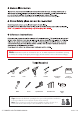
PARTS LIST A FOR SHOWER/BATHTUB DOOR 15 16 Keep small parts away from children PACKING LIST Aluminum Threshold 1pc Wall Plugs-B 4pcs Bottom Guide 1pc Wall Brackets(L/R) x 1 for each 1set Wall Plugs-A 2pcs Screws ST5x2" 4pcs Screws ST4x1" 2pcs Rollers 4pcs Gasket-A 2pcs Anti-Lift Pins 4pcs Gasket-B 2pcs Running Bar 1pc Door Panels 2pcs Gasket-C 2pcs Towel Bar 2pcs Allen Wrenches 1pc SP SHOWER AND TUB DOOR MANUAL ����.V �.
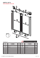
INSTALLATION STEPS STEP � Open Width ±0.0 XXX ±0.0 Threshold must be level Wall must be plumb NOTE: This model does not have adjustment for out-of-plumb conditions minimum 3” of flat threshold space SP SHOWER AND TUB DOOR MANUAL 3/8”from front edge of the threshold if space enough ����.V �.
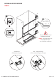
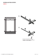
INSTALLATION STEPS STEP � A 14 A B 1 B Measure the drip rail with a tape measure. Cut the length according to installer's recommendation. SP SHOWER AND TUB DOOR MANUAL ����.V �.
INSTALLATION STEPS STEP �A A INTERIOR SHOWER SIDE 14 2 1 1/4" 1 1/2L A 1 Center the bottom guide and drill screw hole on it. 1 3 SP SHOWER AND TUB DOOR MANUAL ����.V �.
INSTALLATION STEPS STEP �B Screws ST4x1" 2 Screws ST4x1" outside 1 outside 2 1 Center SP SHOWER AND TUB DOOR MANUAL ����.V �.
INSTALLATION STEPS STEP � A 2 CENTE R L IN E CENTERLINE B B A SP SHOWER AND TUB DOOR MANUAL ����.V �.
INSTALLATION STEPS STEP � Table Shower Height ��” See Table For Dimension ��” Wall Bracket Bottom Line Height A A Screw ST4x1" SP SHOWER AND TUB DOOR MANUAL ����.V �.
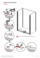
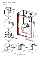
INSTALLATION STEPS STEP � 10 A B A CENTERLINE B A B CENTERLINE CENTERLINE 5/16" 9 B B 12 10 11 Screw ST5x2" 14 Screw Cap View from inside Adjust top rail until it level. SP SHOWER AND TUB DOOR MANUAL ����.V �.
INSTALLATION STEPS STEP �A A 7 14 A A A Anti-Lift Pins 13 SP SHOWER AND TUB DOOR MANUAL ����.V �.
INSTALLATION STEPS STEP �B 7 B1 6 REMARK: B�.Refer to B� for install with water deflectors on the bottom of glass panel. B�.Refer to B� for install without water deflectors remove �mm plastic piece and replace with �mm plastic piece. WARMLY NOTICE: Sliding without water deflectors is smoother. However, there will be a potential water leak. B B2 2mm 4mm 2 SP SHOWER AND TUB DOOR MANUAL ����.V �.
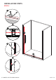
INSTALLATION STEPS STEP � OUTSIDE DOOR INSIDE DOOR Carefully slide the door toward the wall and check the door is sliding smoothly. Adjust if necessary using offset in rollers, so that the sliding door is parallel to the tray. roller eccentric nut 7 cap 12 adjustment disk HOW TO ADJUST Step � : Remove cap from roller cap Step � : Loosen center bolt with hex wrench Step � : Rotate to adjust panel angle with hex wrench Step � : Tighten center bolt SP SHOWER AND TUB DOOR MANUAL ����.V �.
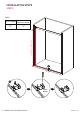
INSTALLATION STEPS STEP � A1 5 7 A1 A2 A1 A2 15 15 A1 B 7 5 B View from inside SP SHOWER AND TUB DOOR MANUAL ����.V �.
INSTALLATION STEPS STEP �� �� HOURS SP SHOWER AND TUB DOOR MANUAL ����.V �.