
Getting Started Guide

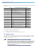

Table Of Contents
- Cisco Catalyst 9130AX Series Access Points
- 1 About this Guide
- 2 About the Cisco Catalyst 9130AX Series Wireless Access Point
- 3 Safety Instructions
- 4 Unpacking
- 5 AP Views, Ports, and Connectors
- 6 Preparing the AP for Installation
- 7 Installation Overview
- 8 Performing a Pre-Installation Configuration
- 9 Mounting the Access Point
- 10 Powering the Access Point
- 11 Configuring and Deploying the Access Point
- 12 Checking the Access Point LEDs
- 13 Miscellaneous Usage and Configuration Guidelines
- 14 FAQs
- 15 Related Documentation
- 16 Declarations of Conformity and Regulatory Information
- Manufacturers Federal Communication Commission Declaration of Conformity Statement
- VCCI Statement for Japan
- Guidelines for Operating Cisco Catalyst Access Points in Japan
- Statement 371—Power Cable and AC Adapter
- Industry Canada
- Canadian Compliance Statement
- European Community, Switzerland, Norway, Iceland, and Liechtenstein
- Declaration of Conformity for RF Exposure
- Generic Discussion on RF Exposure
- This Device Meets International Guidelines for Exposure to Radio Waves
- This Device Meets FCC Guidelines for Exposure to Radio Waves
- This Device Meets the Industry Canada Guidelines for Exposure to Radio Waves
- Cet appareil est conforme aux directives internationales en matière d'exposition aux fréquences radioélectriques
- Additional Information on RF Exposure
- Administrative Rules for Cisco Catalyst Access Points in Taiwan
- Operation of Cisco Catalyst Access Points in Brazil
- Declaration of Conformity Statements
- Communications, Services, and Additional Information
- Cisco Bug Search Tool

5
Cisco Catalyst 9130AX Series Access Points
AP Model Numbers and Regulatory Domains
You need to verify whether the AP model you have is approved for use in your country. To verify approval and to identify
the regulatory domain that corresponds to a particular country, visit http://www.cisco.com/go/aironet/compliance. Not
all regulatory domains have been approved. As and when they are approved, this compliance list will be updated.
Antennas and Radios
The 9130AX series access point configurations are:
C9130AXI-x
C9130AXI-EWC-x
C9130AXE-x
C9130AXE-EWC-x
Internal Antennas
The 9130AXI models (C9130AXI-x and C9130AXI-EWC-x) have four internal dual-band antennas with a dedicated
2.4 GHz radio and a 5 GHz radio, four internal single-band antennas with a dedicated 5 GHz radio, one internal
single-band antenna with a dedicated 2.4 GHz IOT radio, and one dual-band antenna with a dedicated 2.4 GHz radio
and a 5 GHz AUX radio.
External Antennas
The 9130AXE models (C9130AXE-x and C9130AXE-EWC-x) support up to eight external antennas. These include four
dual-band antennas and four single-band 5 GHz antennas.
The 9130AXE model has an 8-port Smart Antenna (DART) connector on its side. External antennas including the Self
Identifying Antennas (SIA) can be connected to this Smart Antenna connector using the 8-port DART cable connector
(AIR-CAB002-D8-R=).
The 9130AXE also supports Smart antennas.
Note Always connect the antennas to the AP before powering the AP up. Enabling the AP radios without
connecting the antennas can result in damage to the AP.
AP Type Model Number Details
Access Point for indoor
environments, with internal
antennas
C9130AXI-x Dual-band, controller-based 802.11ax
C9130AXI-EWC-x C9130AXI-x with a Cisco Embedded
Wireless Controller software image
Access Point for indoor
environments, with external
antennas
C9130AXE-x Dual-band, controller-based 802.11ax
C9130AXE-EWC-x C9130AXE-x with a Cisco Embedded
Wireless Controller software image