GETTING STARTED GUIDE Cisco Catalyst 9130AX Series Access Points First Published: October 25, 2019 Cisco Systems, Inc. 1 www.cisco.
Cisco Catalyst 9130AX Series Access Points 1 About this Guide 2 About the Cisco Catalyst 9130AX Series Wireless Access Point 3 Safety Instructions 4 Unpacking 5 AP Views, Ports, and Connectors 6 Preparing the AP for Installation 7 Installation Overview 8 Performing a Pre-Installation Configuration 9 Mounting the Access Point 10 Powering the Access Point 11 Configuring and Deploying the Access Point 12 Checking the Access Point LEDs 13 Miscellaneous Usage and Configuration Guidelines 15 Re
Cisco Catalyst 9130AX Series Access Points 1 About this Guide This guide provides instructions on how to install your Cisco Catalyst 9130AX series access point and provides links to resources that can help you configure it. This guide also provides mounting instructions and troubleshooting information. Note that the 9130AX series access point is referred to as the access point or the AP in this document.
Cisco Catalyst 9130AX Series Access Points — One multi-color LED Status indicator. see the “Checking the Access Point LEDs” section on page 23 for information on the colors of the LED status indicator. Integrated Bluetooth Low Energy (BLE) radio to enable IoT use cases such as location tracking and wayfinding.
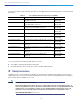
Cisco Catalyst 9130AX Series Access Points AP Model Numbers and Regulatory Domains AP Type Model Number Details Access Point for indoor environments, with internal antennas C9130AXI-x Dual-band, controller-based 802.11ax C9130AXI-EWC-x C9130AXI-x with a Cisco Embedded Wireless Controller software image Access Point for indoor environments, with external antennas C9130AXE-x Dual-band, controller-based 802.
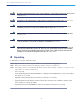
Cisco Catalyst 9130AX Series Access Points The radio and antennas support frequency bands 2400–2500 MHz and 5170–5835 MHz through a common dual-band RF interface. Table 0-1 List of External Antennas Supported on C9130AXE Part Number Description Gain C-ANT9101 Ceiling Mount Omni Self-Identifying Antenna, 8-port, with DART connectors. 2 dBi (2.4 GHz) 4 dBi (5 GHz) C-ANT9102 Pole or Wall Mount Omni Self-Identifying Antenna, 8-port, with DART connectors. 4 dBi (2.
Cisco Catalyst 9130AX Series Access Points Warning Read the installation instructions before using, installing or connecting the system to the power source. Statement 1004 Warning Installation of the equipment must comply with local and national electrical codes. Statement 1074 Warning In order to comply with FCC radio frequency (RF) exposure limits, antennas should be located at a minimum of 12 inches (30 cm) or more from the body of all persons.
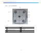
Cisco Catalyst 9130AX Series Access Points 5 AP Views, Ports, and Connectors Figure 1 Face of the 9130AXI Model 1 Status LED 2 Location of the ports and connectors on the head of the AP. Figure 2 3 USB 2.0 port Ports and Connectors on the Head of the 9130AXI Model 1 Kensington lock 4 RJ-45 console port 2 Security hasp for padlocking AP to mounting bracket 5 5 GbE port 3 Mode button 6 USB 2.
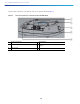
Cisco Catalyst 9130AX Series Access Points Figure 3 Face of the 9130AXE Model 1 Dual-band antenna connector A 5 Status LED 2 Dual-band antenna connector B 6 Location of the ports and connectors on the head of the AP 3 Dual-band antenna connector C 7 USB 2.
Cisco Catalyst 9130AX Series Access Points The ports and connections on the bottom of the access point are shown in Figure 2. Figure 4 Ports and Connections on the Head of the 9130AXE Model 1 RJ-45 console port 2 5 GbE port 3 4 Mode button 5 Security hasp for padlocking AP to mounting bracket USB 2.0 port.
Cisco Catalyst 9130AX Series Access Points d C9130AXI (Internal Antenna) The C9130AXI access point is equipped with four integrated, dual-band antennas omnidirectional in azimuth, for both 2.4 GHz and 5 GHz bands. Figure 3-5 C9130AXI - Dual-band Antenna radiation pattern (2.
Cisco Catalyst 9130AX Series Access Points Figure 3-6 C9130AXI - Dual-band Antenna radiation pattern (2.
Cisco Catalyst 9130AX Series Access Points Figure 3-7 C9130AXI - AUX Antenna radiation pattern (2.
Cisco Catalyst 9130AX Series Access Points Figure 3-8 C9130AXI - AUX Antenna radiation pattern (2.
Cisco Catalyst 9130AX Series Access Points Figure 3-9 C9130AXI - Bluetooth Antenna radiation pattern (2.
Cisco Catalyst 9130AX Series Access Points Figure 3-10 C9130AXI - Bluetooth Antenna radiation pattern (2.4 GHz Elevation) C9130AXE (External Antenna) The C9130AXE AP models (C9130AXE-x and C9130AXE-EWC-x) are certified for use with external antenna with gains up to 6 dBi (2.4 GHz and 5 GHz). They also support Self Identifying Antennas (SIA) on the 8-DART connector. Note Always connect the antennas to the AP before powering the AP up.
Cisco Catalyst 9130AX Series Access Points 6 Preparing the AP for Installation Before you mount and deploy your access point, we recommend that you perform a site survey (or use the site planning tool) to determine the best location to install your access point. You should have the following information about your wireless network available: Access point locations. Access point mounting options: below a suspended ceiling, on a flat horizontal surface, or on a desk top.
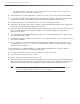
Cisco Catalyst 9130AX Series Access Points 8 Performing a Pre-Installation Configuration The following procedures ensure that your access point installation and initial operation go as expected. This procedure is optional. Note Performing a pre-installation configuration is an optional procedure. If your network controller is properly configured, you can install your access point in its final location and connect it to the network from there.
Cisco Catalyst 9130AX Series Access Points d. Make sure DHCP is enabled on the network. The access point must receive its IP address through DHCP. Note An 802.11ax Cisco AP will be assigned an IP address from the DHCP server only if a default router (gateway) is configured on the DHCP server (enabling the AP to receive its gateway IP address) and the gateway ARP is resolved. e. CAPWAP UDP ports must not be blocked in the network. f. The access point must be able to find the IP address of the controller.
Cisco Catalyst 9130AX Series Access Points Note When you are installing a Layer 3 access point on a different subnet than the Cisco Wireless Controller, be sure that a DHCP server is reachable from the subnet on which you will be installing the access point, and that the subnet has a route back to the Cisco Wireless Controller. Also be sure that the route back to the Cisco Wireless Controller has destination UDP ports 5246 and 5247 open for CAPWAP communications.
Cisco Catalyst 9130AX Series Access Points 9 Mounting the Access Point Cisco Catalyst 9130AX series access points can be mounted in several configurations – on a suspended ceiling, on a hard ceiling or wall, on an electrical or network box, and above a suspended ceiling. For access point mounting instructions, go to the following URL: http://www.cisco.com/c/en/us/td/docs/wireless/access_point/mounting/guide/apmount.html The standard mounting hardware supported by the AP is listed in Table 1.
Cisco Catalyst 9130AX Series Access Points 10 Powering the Access Point Note Always connect the antennas to the 9130AXE before powering the AP up. Enabling the AP radios without connecting the antennas can result in damage to the AP. The AP can be powered only through Power-over-Ethernet (PoE) using the following: 802.3at (PoE+): Any 802.3at (30.0 W) compliant switch port or Cisco Power Injector AIR-PWRINJ6= 802.3af: Any 802.3af (15.
Cisco Catalyst 9130AX Series Access Points access point receives an IP address and DNS information from a DHCP server, it contacts the DNS to resolve CISCO-CAPWAP-CONTROLLER.localdomain. When the DNS sends a list of controller IP addresses, the access point sends discovery requests to the controllers. Deploying the Access Point on the Wireless Network After you have mounted the access point, follow these steps to deploy it on the wireless network: Step 1 Connect and power up the access point.
Cisco Catalyst 9130AX Series Access Points Table 2 LED Status Indications (continued) Message Type LED State Message Meaning Boot loader status Green Executing boot loader Boot loader error Blinking Green Boot loader signing verification failure Operating status Blinking Blue Software upgrade in progress Alternating between Green and Red Discovery/join process in progress Cycling through Red-Off-Green-Off-Blue-Off Access point location command invoked from controller web interface.
Cisco Catalyst 9130AX Series Access Points Controller software enables you to configure the access points to send all CAPWAP-related errors to a syslog server. You do not need to enable any debug commands on the controller because all of the CAPWAP error messages can be viewed from the syslog server itself. The state of the access point is not maintained on the controller until it receives a CAPWAP join request from the access point.
Cisco Catalyst 9130AX Series Access Points CAPWAP does not support Layer 2. The access point must get an IP address and discover the controller using Layer 3, DHCP, DNS, or IP subnet broadcast. The access point console port is enabled for monitoring and debug purposes. All configuration commands are disabled when the access point is connected to a controller.
Cisco Catalyst 9130AX Series Access Points For example, suppose that there are two controllers with management interface IP addresses, 10.126.126.2 and 10.127.127.2. The type is f1(hex). The length is 2 * 4 = 8 = 08 (hex). The IP addresses translate to 0a7e7e02 and 0a7f7f02. Assembling the string then yields f1080a7e7e020a7f7f02. The resulting Cisco IOS command added to the DHCP scope is option 43 hex f1080a7e7e020a7f7f02.
Cisco Catalyst 9130AX Series Access Points 14 FAQs What is 802.11ax? The IEEE 802.11ax standard, also known as the High-Efficiency Wireless (HEW) or Wi-Fi 6, builds off of the 802.11ac and delivers a better experience in typical environments, and a more predictable performance for advanced applications such as 4K or 8K video, high-density high-definition collaboration applications, all-wireless offices and Internet-of-Things (IoT). 802.11ax is designed to use both 2.
Cisco Catalyst 9130AX Series Access Points Figure 13 Smart Antenna Connector C9130AXE Model Figure 14 AIR-CAB002-DART-R= DART Connector What is Cisco Multigigabit Ethernet? Cisco Multigigabit Ethernet (mGig) is a unique Cisco innovation also available in the Cisco Catalyst 9130AX series access point. With the increasing popularity of 802.11ax and new wireless applications, wireless devices now require more network bandwidth.
Cisco Catalyst 9130AX Series Access Points 15 Related Documentation All user documentation for the Cisco Catalyst 9130AX series access point is available at the following URL: http://www.cisco.com/c/en/us/support/wireless/aironet-9130AX-series-access-points/tsd-products-support-serieshome.html For detailed information and guidelines for configuring and deploying your access point in a wireless network, see the following documentation: Cisco Wireless Controller Configuration Guide, Release 8.
Cisco Catalyst 9130AX Series Access Points This equipment has been tested and found to comply with the limits of a Class B digital device, pursuant to Part 15 of the FCC Rules. These limits are designed to provide reasonable protection against harmful interference when the equipment is operated in a residential environment. This equipment generates, uses, and radiates radio frequency energy, and if not installed and used in accordance with the instructions, may cause harmful interference.
Cisco Catalyst 9130AX Series Access Points Guidelines for Operating Cisco Catalyst Access Points in Japan This section provides guidelines for avoiding interference when operating Cisco Catalyst access points in Japan. These guidelines are provided in both Japanese and English.
Cisco Catalyst 9130AX Series Access Points Statement 371—Power Cable and AC Adapter English Translation When installing the product, please use the provided or designated connection cables/power cables/AC adaptors. Using any other cables/adaptors could cause a malfunction or a fire. Electrical Appliance and Material Safety Law prohibits the use of UL-certified cables (that have the “UL” shown on the code) for any other electrical devices than products designated by CISCO.
Cisco Catalyst 9130AX Series Access Points Table 3-2 List of Internal Antennas Supported on C9130AXI Antenna Type Antenna Gain Antenna Impedance Single-Port Single-Band Omni (VPOL) BLE/IOT 4 dBi 50 ohms Single-Port Dual-Band Omni (VPOL) AUX 2.
Cisco Catalyst 9130AX Series Access Points Declaration of Conformity for RF Exposure This section contains information on compliance with guidelines related to RF exposure.
Cisco Catalyst 9130AX Series Access Points As such the systems are designed to be operated as to avoid contact with the antennas by the end user. It is recommended to set the system in a location where the antennas can remain at least a minimum distance as specified from the user in accordance to the regulatory guidelines which are designed to reduce the overall exposure of the user or operator.
Cisco Catalyst 9130AX Series Access Points Par conséquent, les systèmes sont conçus pour être exploités en évitant que l'utilisateur n'entre en contact avec les antennes. Il est recommandé de poser le système là où les antennes sont à une distance minimale telle que précisée par l'utilisateur conformément aux directives réglementaires qui sont conçues pour réduire l'exposition générale de l'utilisateur ou de l'opérateur. Distance d'éloignement Fréquence MPE Distance 2.4 GHz 2.07 W/m 2 5 GHz 3.
Cisco Catalyst 9130AX Series Access Points Administrative Rules for Cisco Catalyst Access Points in Taiwan This section provides administrative rules for operating Cisco Catalyst access points in Taiwan. The rules for all access points are provided in both Chinese and English.
Cisco Catalyst 9130AX Series Access Points Chinese Translation English Translation Low-power Radio-frequency Devices Technical Specifications 4.7 Unlicensed National Information Infrastructure 4.7.5 Within the 5.25-5.35 GHz band, U-NII devices will be restricted to indoor operations to reduce any potential for harmful interference to co-channel MSS operations. 4.7.6 The U-NII devices shall accept any interference from legal communications and shall not interfere the legal communications.
Cisco Catalyst 9130AX Series Access Points Communications, Services, and Additional Information Figure 15 Brazil Regulatory Information Portuguese Translation Este equipamento não tem direito à proteção contra interferência prejudicial e não pode causar interferência em sistemas devidamente autorizados. English Translation This equipment is not entitled to the protection from harmful interference and may not cause interference with duly authorized systems.
Cisco Catalyst 9130AX Series Access Points Cisco Bug Search Tool Cisco Bug Search Tool Cisco Bug Search Tool (BST) is a web-based tool that acts as a gateway to the Cisco bug tracking system that maintains a comprehensive list of defects and vulnerabilities in Cisco products and software. BST provides you with detailed defect information about your products and software. © 2019 Cisco Systems, Inc. All rights reserved.
Cisco Catalyst 9130AX Series Access Points 42