E Rugged Smart Handheld Terminal IT-G600 IT-G650 Series User’s Guide Be sure to read “Safety Precautions” inside this guide before trying to use your Rugged Smart Handheld Terminal.
Trademarks and Licenses Bluetooth is a registered trademark owned by Bluetooth SIG, Inc. and licensed to CASIO COMPUTER CO., LTD. Google™, the Google logo, Android™ and the Android logo are trademarks or registered trademarks of Google LLC. SD, SDHC, SDXC, microSD, microSDHC and microSDXC are trademarks of SD-3C LLC. FeliCa is a registered trademark of Sony Corporation. All other company or product names mentioned herein are trademarks or registered trademarks of their respective owners.
Contents Important ........................................................................................................... 2 Warning Label ................................................................................................... 2 Safety Precautions ........................................................................................... 3 Regulatory Information .................................................................................... 8 Operating Precautions ......................
Important • Information in this document is subject to change without advance notice. CASIO Computer Co., Ltd. makes no representations or warranties with respect to the contents or use of this manual and specifically disclaims any express or implied warranties of merchantability or fitness for any particular purpose. • The descriptions in this manual apply to multiple handheld terminals. Unless otherwise specified, the IT-G600 is used in the descriptions, sample screens and illustrations.
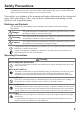
Safety Precautions Congratulations upon your selection of this CASIO product. Be sure to read the following Safety Precautions before trying to use it for the first time. Your neglect or avoidance of the warning and caution statements in the subsequent pages causes the danger of fire, electric shock, malfunction and damage on the goods as well as personal injury. Markings and Symbols The following are the meanings of the markings and symbols used in these Safety Precautions.
Warning Avoid contact with fire • Do not bring the terminal into contact with fire. Doing so could cause the battery to burst and result in a fire or injury. Prohibitions Storage and Operation Locations Do not store or use the product in any of the locations described below. • Areas subjected to large amounts of moisture and dust.
Using the Wireless Data Communication Function Warning Interference with the Operation of Other Equipment (Using Wireless Data Communication) • Should you notice radio interference or other problems on other devices is being caused while using this product, do not use the wireless function. • When using the product in a medical facility or aircraft, follow the instructions of local personnel and crew concerning use of such devices. Do not use the product in an area where use of such devices is prohibited.
Warning Prohibitions Immediately after noticing any fluid leak, abnormal odor, overheating, discoloration, deformation or other battery abnormality, very carefully remove the battery from the product and/or charger. Keep the removed battery away from fire. Do not use a battery exhibiting any abnormality. • If the amount of time period the battery pack can serve becomes considerably short even after it has been fully charged for the specified time period, stop using it.
Caution Unplug from the power supply • Check that the connector is properly oriented and then push it straight in (do not insert upside down). • Do not allow fluids or foreign objects to get into the AC adapter. • Choose a location where the power cord is readily accessible and can be easily plugged in and unplugged. • When using the AC adapter, always use a power outlet with the specified power supply and voltage, and ensure that the power plug is inserted into the socket fully and securely.
Regulatory Information Europe IT-G600 IT-G650 Options of IT-G600/IT-G650 Manufacturer: CASIO COMPUTER CO., LTD. 6-2, Hon-machi 1-chome, Shibuya-ku, Tokyo 151-8543, Japan Importer Casio Europe GmbH Casio-Platz 1, 22848 Norderstedt, Germany www.casio-europe.com • Please keep all information for future reference. • The full text of the EU declaration of conformity is available at the following internet address: http://doc.casio.com/ • Products are for distribution within all member states of the EU.
• The power-supply terminals and Data Communication terminals should be cleaned periodically using an implement such as a dry cotton bud. Soiling on the terminals may cause connection defects. • Take care when using chemicals. Applying thinners, gasoline, kerosene, solvents or oils, or substances such as cleaners, adhesives, paints, medications or toiletries that contain those materials, to the plastic case or cover may cause discoloration or other damage.
• Drop resistance The drop resistance is a test value only and is not guaranteed. Repeated or frequent shocks may still result in damage, so the terminal should be handled so as to avoid impacts. • Water or other moisture on the power-supply or data communication terminals could cause sparking or an electric shock, and soiled contacts could block the connection and impair charging functionality.
About the Waterproofing/Dustproofing The IT-G600/IT-G650 Series models are waterproof and dustproof. Important! The water- and dust-proofing performance of this product is based on CASIO testing procedures. Note also that this performance applies to the product at the time of shipment (delivery to the customer) and is not guaranteed inclusive of the environment in which the product is used.
Accessories and Options Rugged Smart Handheld Terminal IT-G600 Series Rugged Smart Handheld Terminal IT-G650 Series Accessories Make sure all items listed below are included before using the terminal for the first time.
Part Names Terminal (IT-G600) 22 23 (With the battery pack cover fitted) 4 1 2 3 24 15 19 16 16 20 17 5 26 27 28 29 25 32 29 21 18 6 7 8 9 10 11 7 14 13 12 30 31 (With the battery pack cover removed) 36 33 35 34 The illustration shows IT-G600-WC21.
No. Name Description 1 Receiver Outputs audio. 2 Charging Status LED Shows the charging status or battery status. 3 Notification LED Shows notifications. 4 Illuminance/ Proximity Sensor Measures the brightness or the proximity of an object. 5 Screen/Touch Panel Displays text and operating instructions, etc. Can also be used to operate the terminal and enter data. 6 Center Trigger Key Used for scanning barcodes. Can also be assigned to any function.
No. Name Description 26 NFC Reader Reads data from designated cards held over the reader. 27 Speaker Outputs alarm tones and other sounds. 28 Hand Belt Mount Used to attach the Hand Belt. 29 Battery Pack Cover Lock Switches Slided to open or close the battery cover. 30 Battery Pack Cover The battery pack is installed inside this cover. 31 Hand Belt Mount/ Strap Hole Used to attach the neck strap or hand belt. 32 Rear Microphone Used for Noise Canceling.
Terminal (IT-G650) 15 16 (With the battery pack cover fitted) 4 1 2 3 17 8 12 9 9 13 10 5 19 20 21 22 18 25 22 14 11 23 6 7 24 (With the battery pack cover removed) 29 26 28 27 The illustration shows IT-G650-W21.
No. Name Description 1 Receiver Outputs audio. 2 Charging Status LED Shows the charging status or battery status. 3 Notification LED Shows notifications. 4 Illuminance/ Proximity Sensor Measures the brightness or the proximity of an object. 5 Screen/Touch Panel Displays text and operating instructions, etc. Can also be used to operate the terminal and enter data. 6 Function Key Used to launch applications registered beforehand. 7 Microphone Inputs audio.
No. Name Description 27 Reset Switch Performs a hardware reset. 28 nanoSIM Card Slot Used to load a nanoSIM card. 29 Connects to the terminals in a cradle or similar device to supply Power Supply/ Data Communication Terminals power or enable USB communication. Getting Ready to Use * In the step 3, be sure to charge the battery pack completely. 1. Confirm that all the items listed on page 12 are included in the package. 2. Install the supplied battery pack in the terminal. (→page 18) 3.
• The charge of a battery pack when you purchase it may be depleted due to testing at the factory or natural discharge during shipment and storage. Be sure to charge the battery pack before you use it. • The life of a battery pack is limited, and charging a battery pack causes it to gradually lose its ability to maintain the charge. If your battery pack seems to require charging very frequently, it probably means it is time to purchase a new one.
3. Replace the battery pack cover ( ) as shown in the illustration. 4. Press down on the battery pack cover so that it is securely closed. 5. Return the left and right battery pack cover lock switches to the “LOCK” position ( Precautions for Use ). • Do not use any battery packs other than the specified one. • The battery pack has a limited service life. Depending on the way the battery pack is charged, its degradation may accelerate or its capacity be reduced so that it cannot be used for as long.
Replacement 1. Turn the screen on. 2. Hold down the Power key until the Power menu is displayed. 3. Tap “Hot swap” as shown in the figure. Hot swap 4. Tap “OK” as shown in the figure and the terminal will switch to the Hot Swap mode. This causes the notification LED to light red. Once switching is completed, the notification LED turns off. 5. Turn the terminal over, turn the left and right battery pack cover lock switches to the “FREE” position ( ) and remove the battery pack cover ( ). 6.
Precautions for Use • In the Hot Swap mode, even if the battery pack is removed, your work state is saved up to 4 minutes with the memory (RAM) backup function. The memory (RAM) backup time may decrease depending on the backup battery charging level. • In the Hot Swap mode, the terminal will not respond even if you press the Power key. To exit Hot Swap mode, open the battery cover and then close it again.
Charging the Battery Pack You can charge the battery pack while it is installed in the terminal using the optional USB cradle, Ethernet cradle or multiple battery charger. Check charging status LED to confirm the terminal charging status. You can also use the USB cradle, Ethernet cradle or dual battery charger to charge the battery pack.
Charging the battery pack Cradle charging status LED display Red: Charging Green: Charging complete Red/green alternate flashing: Standby because the battery pack is faulty, is installed incorrectly or is outside the charging temperature range (Charging begins when Cradle charging status temperature returns to the LED charging temperature range) As shown in the illustration, insert the battery pack so that markings on the cradle and battery pack are aligned.
Multiple Battery Charger AD-S12500A • You can connect up to three Multiple Battery Chargers. Terminal charging status LED display Orange: Green: Red: Charging Charging complete Standby due to battery pack error or because the ambient temperature is outside the charging temperature range. (Charging begins when the temperature returns to the charging temperature range.) Red flashing: Charging (The terminal cannot start up because the charge remaining in the battery pack is too low.
Using the Stylus Retaining Cord Use the procedure below to attach the stylus retaining cord. 1 Thread the cord through the hole at the top of the stylus. 2 Thread the other end of the cord through the loop. Attaching the Neck Strap and Stylus Use the procedure below to attach the neck strap or stylus to the strap holes. There are 3 strap holes in the terminal (see pages 13 to 17). Attach the hand strap or stylus in the position that makes it easiest for you to use the terminal.
Attaching the Hand Belt How to attach the Hand Belt 1. Push the metal hand belt fitting so that it engages with the mount on the terminal, as shown in the illustration. Check that the fitting is securely attached. 2. Feed the end of the hand belt through the hand belt mount, fold it back to a suitable length and then fasten it using the hook and loop fastener.
Using a nanoSIM Card IT-G600/IT-G650 supports nanoSIM cards. To use WAN functions, a nanoSIM card must be installed. The nanoSIM card slot is located in the battery pack compartment, so you must remove the battery pack before installing or removing a nanoSIM card. Installation 1. Turn the terminal off (shutdown). 2. Remove the battery pack. (Steps 5 and 6 in the battery pack replacement procedure on page 21) 3 Push in the stylus (opposite end) in direction direction .
5 Insert the nanoSIM card tray in the direction indicated by the arrow. 6. Install the battery pack. (Steps 2 and 3 in the battery pack installation procedure on page 19) Removal 1. Turn the terminal off (shutdown). 2. Remove the battery pack. (Steps 5 and 6 in the battery pack replacement procedure on page 21) 3 Remove the nanoSIM card tray. (Step 3 on page 28) 4 Remove the nanoSIM card from the nanoSIM card tray. 5 Install the nanoSIM card tray in the terminal. 6. Install the battery pack.
Using a microSD Card IT-G600/IT-G650 supports micro SD cards. The microSD card slot is located in the battery pack compartment, so you must remove the battery pack before installing or removing a microSD card. Installation 1. Turn the terminal off (shutdown). 2. Remove the battery pack. (Steps 5 and 6 in the battery pack replacement procedure on page 21) 3. Push the microSD card into the card slot until it is fully inserted, as shown in the figure. 4. Install the battery pack.
Using the Laser Scaner 1. After turning on the power, position the barcode reader close to a bar code and then press the trigger key. 2. The laser emits light and scans the bar code. If scanning is completed normally, Notification LED displays a green light. Precautions for Use • If you have problem not properly reading a code, change the angle and/or the distance between the code and the terminal and try reading it again. • A bar code can be read from a distance of 33mm to 630mm.
Handling the NFC The NFC is a technology of contactless IC card for short range communication that enables writing data to card and reading data from the card by applying the card close to the NFC Reader. The integrated NFC can read a contactless IC card used typically for employment identification, etc. 1. Hold the card flat against the NFC reader on the back of the terminal (near the center of the battery cover). Precautions for Use • Do not apply card while it is overridden by other card.
Making the Touch Panel Easier to Use You can adjust the sensitivity of your terminal’s touch panel. You can choose from 4 levels of touch panel sensitivity: “Wet Touch”, “Normal Touch”, “Comfort Glove Touch” and “Cotton Glove Touch”. If you are finding the touch panel difficult to operate, select the touch panel sensitivity that best suits your situation. Configuration procedure: “Settings” → “Accessibility” → “Touch Sensitivity” Circles ( ) in the table below denote recommended settings.
Turning the Power On/Off and Sleep Turning the Power On 1. Hold down the Power key until the terminal vibrates. • The startup screen is displayed. Precautions for Use • Be sure to completely charge the battery pack before turning the power on for the first time after the purchase. • If the terminal does not start even after power is turned on, remaining power of the battery pack may be low. Completely charge the battery pack and then turn the power on again. Turning the Power Off (Shutdown) 1.
Performing Communications Bluetooth® Communication Bluetooth® interface can also be used to transfer data between two terminals. With Bluetooth® the two terminals should be located within about five meters from each other, as long as there is nothing blocking the path between them. Important! Observe the following precautions to help ensure that Bluetooth communication is successful. • Make sure two terminals face each other within five meters.
Rebooting or Resetting the Terminal If the terminal no longer operates normally due to a problem such as an operating error or severe impact, use the procedure below to attempt to restore normal operation. 1. Reboot 2. Forced Reboot 3. Reset Reboot 1. With the screen turned on, hold down the Power key until the Power menu is displayed. 2. Tap “Reboot”. Forced Reboot 1. Hold down the Power key until the terminal vibrates (approx.12 seconds). Reset 1. Open the battery cover and remove the battery pack. 2.
IT-G600/G650 Specifications IT-G600 -WC01 -C21 -C31 -C21-CN IT-G650 -WC21 -WC31 -C21 -C31 CPU Qualcomm 2.2GHz + 1.8GHz Octa Core OS AndroidTM 9 Memory RAM : 4GB ROM : 64GB Display (4.7 inches), 720 × 1280-dot TFT Color LCD Scanner *1 Camera – -WC21 -WC31 Remark (5.5 inches), 720 × 1440-dot TFT Color LCD 2D Scanner (Imager) 13M pixels auto focus Microphone Voice and sound Speaker For voice sound input and voice call at phone WLAN *2 IEEE 802.11a/b/g/n/ac Bluetooth® *3 v5.
IT-G600 -WC01 -C21 -C31 -C21-CN IT-G650 -WC21 -WC31 -C21 -C31 -WC21 -WC31 Drop Durability 1.8m *9 Dust / water-resistance IP67 level External dimensions Approx. 75mm × 180mm × 18mm Approx. 78mm × 180mm × 18mm Weight Approx. 295g Approx. 310g Vibrator Scanner and other notifications Sensors Proximity sensor / Light Ambient sensor / Acceleration sensor / Geomagnetic sensor / Gyro sensor 38 1.
*1 Scanner Specifications Item 2D Scanner Method (Imager) Aimer method Specification CMOS Imager, 1280 × 800, monochrome Laser 650nm, < 1mW Laser emit angle Redirected downward: IT-G600-C21/WC21/C21-CN, IT-G650-C21/WC21: 25 degree IT-G600-C31/WC31, IT-G650-C31/WC31: 60 degree Resolution 1D : 0.127mm 2D Stacked : 0.169mm 2D Matrix : 0.191mm PCS 0.45 (minimum) or greater Readable distance 1D : 33 ~ 420mm (0.25mm resolution) 1D : 37 ~ 630mm (0.50mm resolution) 2D Stacked : 98 ~ 220mm (0.
*2 WLAN Speficications Item WLAN 802.11a/b/ g/n/ac Specification Frequency Range 2412 MHz – 2472 MHz (1 ~ 13ch) 5180 MHz – 5320 MHz (36 ~ 64ch) 5500 MHz – 5700 MHz (100 ~ 140ch) 5745 MHz – 5825 MHz (149 ~ 165ch) (802.11d: Allowed frequency range can be used according to countries or regions.) Baud rate 802.11a/g: 54Mbps (maximum) 802.11b: 11Mbps (maximum) 802.11n HT20 (2.4&5GHz): 72Mbps (maximum) 802.11ac : 433Mbps (maximum) Communication Distance 802.
*4 Wireless WAN Specifications Item LTE W-CDMA GSM Specification Communication Audio, Data Packet Baud rate Downlink: 150Mbps (maximum) Uplink: 50Mbps (maximum) Frequency range Band FDD 1 (1920-1980MHz/2110-2170MHz) FDD 3 (1710-1785MHz/1805-1880MHz) FDD 7 (2500-2570MHz/2620-2690MHz) FDD 8 (880-915MHz/925-960MHz) FDD 19 (830-845MHz/875-890MHz) FDD 20 (832-862MHz/791-821MHz) FDD 26 (814-849MHz/859-894MHz) TDD 38 (2570-2620MHz/2570-2620MHz) TDD 39 (1880-1920MHz/1880-1920MHz) TDD 41 (2496-2690MHz/2496-26
*6 NFC Speficications Item NFC Depth of Field Specification ISO14443 Type A/B, FeliCa: 0 mm (Contact) ISO15693: 0 mm (Contact) ~ 50 mm (Maximum) Remark It can change by the design of Card or Tag *7 According to JEITA G mode LCD backlight brightness minimum, WLAN ON (with stable RF connection), Buzzer minimum, Vibrator OFF, RF OFF (except for WLAN), Power saving setting after scanning (1sec) *8 • Camera Flash is unavailable in –20 ºC ~ –11 ºC.
USB Cradle (HA-U60IO) The USB cradle can be used to connect the IT-G600/IT-G650 to devices such as a computer or USB device. It can also be used to supply power to the IT-G600/IT-G650 and to charge the battery pack. Part Names and Operation 3 6 4 5 1 2 1 AC Adaptor Jack Used to connect an AC adapter as a power supply. 2 USB Client Port Used to connect to a computer. 3 Charging Status LED (Battery Pack) Shows the charging status.
4. Align the terminals on the bottom of the IT-G600/IT-G650 with the power supply terminals in the USB Cradle before inserting the IT-G600/IT-G650 ( ). Push the IT-G600/ IT-G650 fully into the USB Cradle until the mount hooks in the cradle engage the mount holes in the IT-G600/IT-G650 ( ). To remove the IT-G600/IT-G650 from the USB Cradle, tilt the IT-G600/IT-G650 forward to disengage the mount hooks from the mount holes and then lift the IT-G600/IT-G650 out of the cradle.
Ethernet Cradle (HA-U62IO) The optional Ethernet Cradle (HA-U62IO) makes it possible to transmit file data between IT-G600/IT-G650 and a PC via a USB or LAN connection (download or upload). You can also use the Ethernet Cradle to charge the battery pack installed in IT-G600/IT-G650. It can also be used to connect the IT-G600 and IT-G650 to a computer or USB device. Part Names and Operation 6 9 7 8 5 1 2 3 4 1 AC Adaptor Jack Used to connect an AC adapter as a power supply.
Installing and Connecting the Power Supply Use the optional AC adaptor(AD-S50400A) to supply power to the charger. Use the selector switch on the left side of the Ethernet Cradle to select the port to be used. Set the switch to the “LAN” position when using the LAN port on the cradle. Set the switch to the “B” position when using the unit as a USB client, or set it to the “A” position when using the unit as a USB host. 1. Plug the AC adapter into the AC adapter jack on the back of the Ethernet Cradle. 2.
Precautions for Use • Even if the battery in the IT-G600/IT-G650 is already fully charged, charging will begin when you set the IT-G600/IT-G650 in the Ethernet cradle. It may take several minutes for the fully charged status to be indicated. • In high- or low-temperature environments, charging may be restricted to protect the battery pack. At such temperatures, the level of battery charge may not reach 100% even when the charging status LED is green and charging is completed.
Multiple Battery Charger (HA-U36DCHG) The optional Multiple Battery Charger (HA-U36DCHG) can concurrently charge two battery packs installed in IT-G600 and/or IT-G650 terminals.
Accessories Use these bundled items to join multiple chargers together. • Bottom bracket • Side bracket • Screws (for brackets) Two each for one bracket 1 AC Adaptor Jack Connect the AC adaptor (sold separately) here. 2 Power Switch Turns the power on and off. 3 Multiple Battery Charger Connection Port Use these connectors to connect Multiple Battery Chargers to each other. 4 Connection Bracket Attachment Holes Used to connect Multiple Battery Chargers to each other.
Charging Battery Pack Use the optional AC adaptor(AD-S12500A) to supply power to the charger. AD-S12500A 1. Plug the connector from the AC adaptor into the AC adaptor jack on the charger with the engraved side of the connector facing upwards. Push the connector firmly into the jack until it clicks into place. 2. After connecting the power cable to the AC adaptor, plug the other end of it into an AC outlet. 3. Turn on the power switch on the side of the charger.
Connecting Multiple Battery Chargers You can connect up to three Multiple Battery Chargers. Doing so makes it possible to supply power to all the Multiple Battery Chargers using one dedicated AC adaptor. 1. As shown in the illustrations below, remove the connector covers of the Multiple Battery Chargers you want to connect to each other. Connector covers 2. Connect the two Multiple Battery Chargers as shown below. Connectors 3. Fix the side and bottom brackets in place with two screws on each bracket.
Precautions for Use • Each unit of the charger comes with one piece each of the side and bottom brackets. After you join two chargers together using these two brackets, one side bracket and one bottom bracket will be left over. Keep these as spare for use in future. • Always disconnect the AC adaptor before joining multiple chargers together. Specifications 1. Charging specifications Charging method : Constant-voltage constant-current charging Charging time : Approx. 4 hours 2.
Dual Battery Charger (HA-U32DCHG) The optionally available Dual Battery Charger (HA-U32DCHG) can be used to simultaneously charge two battery packs. Part Names and Operation 1 3 2 5 3 4 Accessories Use these bundled items to join multiple chargers together.
1 Charging Status LED 2 AC Adaptor Jack Dual Battery Charger Connection Port Connection Bracket Attachment Holes Battery Pack Contacts 3 4 5 Off: The battery pack is not installed. Red: Charging Green: Charging complete Red/green alternate flashing: Standby because the battery pack is faulty, is installed incorrectly or is outside the charging temperature range (Charging begins when temperature returns to the charging temperature range) Connect the AC adaptor (sold separately) here.
Charging status LED display for the four-bay battery charger Off: The battery pack is not installed. Red: Charging Green: Charging complete Red/green alternate flashing: Standby because the battery pack is faulty, is installed incorrectly or is outside the charging temperature range (Charging begins when temperature returns to the charging temperature range) Connecting Multiple Dual Battery Chargers You can connect up to three Dual Battery Chargers.
Specifications 1. Charging specifications Charging method : Constant-voltage constant-current charging Charging time : Approx. 4 hours 2. AC adapter specifications Standard : AD-S12500A Input : 100-240V AC, 50/60 Hz, 1.5A Output : 12V DC, 5A 3. Dimensions, weight Dimensions Weight : Approx. 104(W) × 114(D) × 71(H) mm : Approx. 205g 4.
Battery Pack (HA-U20BAT) HA-U20BAT Precautions for Use • Store a battery pack in its special soft case whenever you are not using it. • If the battery pack has been left over unused for a long period of time, the capacity remained decreases due to spontaneous discharge or chemical decomposition by the battery pack itself. If the battery pack fails to hold its operating duration after it has been fully charged, replace it with a new one. The battery pack may reach the end of its service life.
CASIO COMPUTER CO., LTD. 6-2, Hon-machi 1-chome Shibuya-ku, Tokyo 151-8543, Japan PN410538-002 PN410538-002 MO2007-B 2020 CASIO COMPUTER CO., LTD.