BEDIENUNGSANLEITUNG OPERATING INSTRUCTIONS NOTICE D’UTILISATION MCW-D 50 Konferenzsystem Discussion System Système de conférence digital sans fil
1. Allgemeine Sicherheitshinweise . . . . . . . . . . . . . . . . . . . . . . . . . . . . . . . . . . . . . . . . . . . . . . . . . . . . . . . . . . . . . . . . . . . . . . . . Seite 4 2. Aufstellung. . . . . . . . . . . . . . . . . . . . . . . . . . . . . . . . . . . . . . . . . . . . . . . . . . . . . . . . . . . . . . . . . . . . . . . . . . . . . . . . . . . . . . . . Seite 6 3. Steuerzentrale MCW-D 50 . . . . . . . . . . . . . . . . . . . . . . . . . . . . . . . . . . . . . . . . . . . . . . .
MCW-D 50 – Sicherheitshinweise 4 Sie haben sich für das drahtlose, digitale Konferenzsystem MCW-D 50 von beyerdynamic entschieden. Wir danken für Ihr Vertrauen. Nehmen Sie sich bitte einige Minuten Zeit und lesen Sie diese Bedienungsanleitung vor Inbetriebnahme aufmerksam durch. In dieser Bedienungsanleitung werden die Installation und Bedienung des Systems ohne Steuerung und Konfiguration über einen PC beschrieben.
Reinigung • Reinigen Sie das Gerät nur mit einem leicht feuchtem oder trockenem Tuch. Verwenden Sie niemals Lösungsmittel, da diese die Oberfläche beschädigen. Fehlerbeseitigung / Reparatur • Öffnen Sie nicht eigenmächtig das Gerät. Sie könnten einen elektrischen Schlag erleiden. • Überlassen Sie alle Servicearbeiten nur autorisiertem Fachpersonal. Ladegerät • Verwenden Sie zum Laden der in den Sprechstellen integrierten Akkus das Ladegerät CD 12, CD 13 bzw. das Netzteil CA 2457.
MCW-D 50 – Steuerzentrale 2. 6 Aufstellung Die Steuerzentrale MCW-D 50 ist zur Aufstellung auf einen Tisch bzw. zum Einbau in ein 19"-Rack vorgesehen. Bei der Aufstellung müssen Sie die Sicherheitsinformationen in Kapitel 1 beachten. Insbesondere und darüber hinaus • • • • • • darf die Umgebungstemperatur am Aufstellungsort 40°C nicht überschreiten. darf der Aufstellungsort keiner übermäßigen Staub- und Feuchtigkeitsentwicklung ausgesetzt sein.
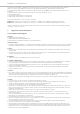
MCW-D 50 – Steuerzentrale 7 19 6 20 7 8 9 10 11 12 13 19 14 15 6 Serielle Schnittstelle RS 232 für Anschluss von z.B. PC oder Mediensteuerung (9-pol. Sub-D). Zum Anschluss ein RS 232 Nullmodem bzw. „Crossover“ Kabel (female - female) verwenden.
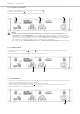
MCW-D 50 – Steuerzentrale 8 3.2.2 Antennen anschließen • Schließen Sie die Empfangsantennen an die Antenneneingänge A und B 19 an. • Schließen Sie die Sendeantenne 20 an. • Für den Stand-Alone-Betrieb empfehlen wir die Stabwinkelantennen CA 2411. 19 20 19 Wichtig: • Antennen und Sprechstellen sollten Sichtkontakt haben, d.h. zwischen der Steuerzentrale MCW-D 50 und den Sprechstellen dürfen keine Hindernisse sein.
MCW-D 50 – Steuerzentrale 3.2.5 Ein-/Ausschalten • Schalten Sie die Steuerzentrale MCW-D 50 mit dem Ein-/Ausschalter 16 auf der Rückseite ein oder aus. • Während der ersten ca. 30 Sekunden wird die Steuerzentrale MCW-D 50 initialisiert, dabei blinken die Power LED 1 sowie die ChannelLEDs 4 rot. In dieser Zeit ist kein Betrieb möglich. Ist die Steuerzentrale MCW-D 50 über den LAN-Anschluss 7 an einem Netzwerk angeschlossen, beträgt die Zeitspanne bis die Steuerzentrale MCW-D 50 betriebsbereit ist ca.
MCW-D 50 – Steuerzentrale 10 3.2.9 Anschluss von Mediensteuersystem und PC • Wenn Sie sowohl ein Mediensteuersystem als auch einen PC an die Steuerzentrale MCW-D 50 anschließen möchten, schließen Sie den PC an den LAN-Netzwerkanschluss 7 und das Mediensteuersystem an den RS 232-Anschluss 6 an. • Für die direkte Verbindung des LAN-Netzwerkanschlusses mit einem PC muss ein RS 232 Nullmodem bzw. „Crossover“-Kabel (female - female) verwendet werden.
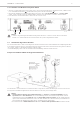
MCW-D 50 – Steuerzentrale Raumgröße: Teilnehmerzahl: Antennenposition: Ausrichtung: bis zu 400 m2 (20 x 20) 30 - 100 am Rand der Sitzposition der Teilnehmer, möglichst hoch über dem Tischniveau Antennen zu den Teilnehmern hin ausrichten (gewölbte Seite nach vorne) Kabeltyp Aircell 7 Standard CA 2420 Ecoflex 10 Low Attenuation CA 2430 Max. Kabellänge bis zu 20 m = 1 x CA 2422 oder 2 x CA 2421 bis 40 m Min.
MCW-D 50 – Sprechstellen 4. 12 Delegierten- und Präsidentensprechstellen • Damit die Steuerzentrale MCW-D 50 die Sprechstellen gezielt steuern kann, wird im Werk jeder Sprechstelle eine individuelle Adresse / Seriennummer einprogrammiert. Diese Adresse / Seriennummer ist auf der Unterseite der jeweiligen Sprechstelle aufgedruckt. • Im Übertragungsprotokoll wird jede Sprechstelle per Funk über eine individuelle ID-Nummer angesprochen.
MCW-D 50 – Sprechstellen 13 5 6 5 Schwanenhalsmikrofon mit Leuchtring 6 Lautsprecher 7 LED zur Funktionsanzeige (grün/rot) 8 Mikrofontaste 9 Clear-Taste zum Löschen der Delegierten-Sprechstellen 10 Programmierbare Funktionstaste (siehe auch Kapitel 5.
MCW-D 50 – Inbetriebnahme 14 4.1.2 Ein-/Ausschalten Delegierte MCW-D 521 Präsident MCW-D 523 Einschalten • Die Sprechstellen haben keinen separaten Ein-/Ausschalter. Sie werden über die Mikrofontaste 8 bzw. 19 ein- und ausgeschaltet. 7 7 8 MCW-D 521 / MCW-D 523 • Durch kurzes Drücken wird die Sprechstelle eingeschaltet. Dabei leuchtet die LED 7 kurz auf und die grüne Betriebskontroll-LED 3 auf der Rückseite leuchtet. MCW-D 531 / MCW-D 533 • Durch kurzes Drücken wird die Sprechstelle eingeschaltet.
MCW-D 50 – Inbetriebnahme Speisung / Betriebszeit deutsch 4.2 15 Rückseite MCW-D 521 / MCW-D 523 • Die Sprechstellen haben einen integrierten Akku, der vollgeladen eine Betriebszeit von ca. 20 Stunden gewährleistet. • Bei nachlassender Spannung, blinkt die Betriebskontroll-LED 3 bzw. 16 auf der Rückseite der Sprechstelle. Die Restbetriebszeit beträgt ca. eine Stunde.
MCW-D 50 – Inbetriebnahme 4.4 16 Betriebsarten • Die verschiedenen Betriebsarten wie Normal, Push-To-Talk oder Sprachaktiviert werden mit der MCW-D 50 Conference Software für alle Sprechstellen gemeinsam eingestellt. Die ab Werk eingestellte Betriebsart ist Normal. Siehe hierzu die entsprechende Bedienungsanleitung MCW-D 50 Conference Software. 4.4.1 Betriebsart Normal Delegierte MCW-D 521 Präsident MCW-D 523 7 7 • Schalten Sie das Mikrofon mit der Mikrofontaste 8 bzw. 19 ein.
MCW-D 50 – Inbetriebnahme Aufzeichnen der Konferenz Rückseite MCW-D 521 / MCW-D 523 • An den Dokumentationsausgang 4 bzw. 14 kann ein Recorder (z.B. Notebook mit steno-s Software) zur Aufzeichnung der Konferenz angeschlossen werden. • Die Lautstärke kann über einen PC mit der MCW-D 50 Conference Software eingestellt werden. • An den Dokumentationsausgang 4 bzw. 14 kann auch ein Kopfhörer angeschlossen werden. Wir empfehlen eine Impedanz von 600 Ω.
MCW-D 50 – Inbetriebnahme 5.2 18 Programmierbare Funktionstaste Präsidentensprechstelle MCW-D 523 / MCW-D 533 Die Funktionstaste 10 bzw. 23 hat je nach Konfiguration eine der folgenden Funktionen: Mute, Löschen oder Priorität. Die Funktionstaste der Präsidentensprechstelle wird drahtlos über die Steuerzentrale mit der MCW-D 50 Conference Software konfiguriert werden. Präsident MCW-D 523 7 10 Präsident MCW-D 533 23 20 21 1.
5.3 19 Betriebsart Anmeldung • Diese Betriebsart funktioniert nur in Verbindung mit einem Bedien-PC und der MCW-D 50 Conference Software oder einem Mediensteuersystem (AMX®, Crestron®, Cue etc.). • Durch Drücken der Mikrofontaste 8 bzw. 19 an der Sprechstelle wird eine Anmeldung im System registriert. • Die Zuteilung erfolgt durch den Bediener am PC oder Touchscreen der Mediensteuerung. • Die LED 7 bzw. 20 leuchtet rot, um die Anmeldung zu signalisieren. • Ein erneutes Drücken der Mikrofontaste 8 bzw.
MCW-D 50 – Inbetriebnahme 6.2 20 Ladevorgang 1. Schließen Sie das Ladegerät ans Netz an und schalten Sie es mit dem Ein-/Ausschalter ein. Der Schalter leuchtet. 2. Schieben Sie die ausgeschalteten Sprechstellen in die Ladefächer. Eventuell noch eingeschaltete Sprechstellen werden automatisch ausgeschaltet. Werden die Sprechstellen wieder dem Ladefach entnommen, müssen sie von Hand eingeschaltet werden. 3.
MCW-D 50 – Problemlösung Akkuladung über externes Netzteil CA 2457 deutsch 8. 21 Rückseite MCW-D 521 / 523 2 • Die MCW-D Sprechstellen können auch über das externe Netzteil CA 2457 geladen werden, welches Sie an die DC-Buchse 2 bzw. 15 anschließen. • Der Ladevorgang wird durch die Betriebskontroll-LED 3 bzw. 16 angezeigt. LED-Anzeige bei Ladevorgang des Akkus: a) LED blinkt rot. . . . . . . . . . . . . . . . . . . . . . . . . . . Akku wird geladen b) LED leuchtet dauerhaft rot. . . . . . . . . . . . .
MCW-D 50 – Problemlösung 22 Problem Mögliche Ursache Lösung Sprechstellenlautsprecher funktioniert nicht • Überprüfen Sie die Lautstärkeeinstellung mit der MCW-D Conference Software • Erhöhen Sie die Lautstärke über die MCW-D Conference Software oder mit dem Volume-Regler an der Steuerzentrale Sprechstelle lässt sich nicht ausschalten • Manuelles Abschalten ist deaktiviert.
MCW-D 50 – Problemlösung 9.1.2 MCW-D und WLAN bzw. WiFi Die HF-Übertragung des MCW-D 50 Systems orientiert sich am WLAN-Standard, d.h. MCW-D 50 nutzt, wie WLAN, eine Bandbreite von ca. 22 MHz für jeden HF-Kanal (Low, Mid, High). Unter Berücksichtigung einer in der Realität nicht möglichen idealen Kanaltrennung, ergibt dies für beide Technologien drei nicht überlappende, kompatible HF-Kanäle im 2,4 GHz-ISM Band. Diese sind theoretisch: Kompatibler Kanal 1: 2400 MHz - 2428 MHz (theoret.
MCW-D 50 – Zubehör 24 9.1.3 MCW-D 50 und Bluetooth • Im Gegensatz zu WLAN und MCW-D 50 nutzen Geräte mit Bluetooth-Übertragung das gesamte 2,4 GHz-ISM Band durch eine ständig wechselnde Trägerfrequenz („Frequency Hopping“). • Durch verschiedene konstruktive Maßnahmen im MCW-D 50 System sowie ein fortgeschrittenes Übertragungsprotokoll sind Störeinflüsse durch Bluetooth-Geräte (auch Mikrowellenherde) im Normalbetrieb weitgehend auszuschließen.
MCW-D 50 – Zubehör CA 2441 T CA CA CA CA 2442 2443 2444 2445 CA 2457 Antennen-Verstärker für Sende- und Empfangsweg, (10 dB Verstärkung), Fernspeisung 5 V über Antennenkabel . . . . . . . . . . . . . . . . . . . . . . . . . . . . . . . . . . . . . . . . Best.-Nr. 470.309 Antennen-Verstärker für Sendeweg, (8 dB Verstärkung), Fernspeisung 5 V über Antennenkabel . . . . . . . . . . . . . . . . . . . . . . . . . . . . . . . . . . . . . . . . Best.-Nr. 470.
MCW-D 50 – Technische Daten Ausgangspegel. . . . . . . . . . . . . . . . . . . . . . . . . . . . . . . . . . . . max. 2,4 V rms im Leerlauf, Klirrfaktor < 1%, 2,3 V rms an 80 Ω Last, Klirrfaktor < 1% Mindestanschlussimpedanz . . . . . . . . . . . . . . . . . . . . . . . . . . 600 Ω Eingebauter Limiter gegen Übersteuerung . . . . . . . . . . . . . . . nicht abschaltbar Limitereinsatz bei . . . . . . . . . . . . . . . . . . . . . . . . . . . . . . . . . . 126 dB SPL Stromversorgung . . . . . . . . . . . . . .
CA 2441 RT Antennenverstärker Frequenzbereich . . . . . . . . . . . . . . . . . . . . . . . . . . . . . . . . . . . 2,4 - 2,485 GHz; mit Filter gegen GSM-Telefone Max. Eingangspegel . . . . . . . . . . . . . . . . . . . . . . . . . . . . . . . . 6 dBm Verstärkung . . . . . . . . . . . . . . . . . . . . . . . . . . . . . . . . . . . . . . 10 dB Stromaufnahme . . . . . . . . . . . . . . . . . . . . . . . . . . . . . . . . . . . ca. 140 mA Speisespannung . . . . . . . . . . . . . . . . . . . . . . . . . . . .
MCW-D 50 – Contents 29 1. Important Safety Instructions . . . . . . . . . . . . . . . . . . . . . . . . . . . . . . . . . . . . . . . . . . . . . . . . . . . . . . . . . . . . . . . . . . . . . . . . . . Page 30 3. MCW-D 50 Control Unit. . . . . . . . . . . . . . . . . . . . . . . . . . . . . . . . . . . . . . . . . . . . . . . . . . . . . . . . . . . . . . . . . . . . . . . . . . . . . . Page 3.1 Controls and Indicators . . . . . . . . . . . . . . . . . . . . . . . . . . . . . . . . . . . . . . . . . .
MCW-D 50 – Important Safety Instructions 30 Thank you for selecting the MCW-D 50 Digital wireless conference system. Please take some time to read carefully through this manual before setting up the equipment. This manual describes the installation and operation of the system without control and configuration via PC.
MCW-D 50 – Important Safety Instructions 31 Maintenance • Only clean the equipment with a slightly damp or dry cloth. Never use solvents as these damage the surface. Charger • Use only the CD 12 charger or CA 2457 power supply unit to charge the rechargeable batteries integrated in the microphone units. • Never remove the base foam section from the CD 12 charger. There are no parts that can be serviced in the interior of the charger.
MCW-D 50 – Important Safety Instructions 32 Special Note about Power Cables for Canada and the USA Canada Only use a power cable according to CSA C22.2 No.21 and CSA C22.2 No. 42. USA The earthing conductor in a supply cord, or in an interconnecting cable shall have an equivalent or larger cross-sectional area that the current-carrying conductors in the supply cord or cable. With reference to earthing conductors, the insulation colour may be green or green/yellow.
MCW-D 50 – Control Unit 2. 33 Installation The MCW-D 50 discussion system has been developed for installation on tables or 19"-mounting. When setting up the system please follow the safety instructions mentioned in chapter 1. • • • • • • the ambient temperature of the installation site must not exceed 40°C. there must not be exceeding dust and humidity at the installation site. that the unit is not exposed to direct sunlight. the connections must be protected against direct access during operation.
MCW-D 50 – Control Unit 34 Rear 19 6 20 7 8 9 10 11 12 13 19 14 15 16 6 RS 232 port for the connection of PC or media control system (9-pin Sub-D). Use a null modem or crossover cable (female - female).
MCW-D 50 – Control Unit 35 3.2.2 How to connect the Antennae • Connect the receiving antennae to the antenna inputs A and B 19 . • Connect the transmitting antenna to the antenna output 20 . • For stand-alone operation we recommend using the CA 2411 angled rod antenna. 20 19 english 19 Important: • There must be an unobstructed path between the microphone units and the antennae, i.e. between the MCW-D 50 control unit and the microphone units there must not be any obstacles.
MCW-D 50 – Control Unit 36 3.2.5 How to switch the Control Unit on/off • Switch on the MCW-D 50 with the On/Off-switch 16 on the rear. • During the first 30 seconds the MCW-D 50 control unit is started, the Power LED 1 and the Channel LEDs 4 are flashing red and an operation is not yet possible. If the MCW-D 50 control unit is connected to a network via the LAN connection 7 , the MCW-D 50 control unit will be ready for operation after approx. 20 seconds.
MCW-D 50 – Control Unit 37 3.2.9 Connection of Media Control System and PC 6 7 Important: • Never access the MCW-D 50 control unit via the media control system and the MCW-D 50 Conference Software simultaneously. In this case a correct function of the system cannot be guaranteed. 3.3 Connecting and Positioning of remote Antennae* The MCW-D 50 control unit can also be operated with remote antennae. Low attenuation connecting cables are available in different lengths.
MCW-D 50 – Control Unit • • • • Size of the room: Number of participants: Antenna position: Alignment: 38 up to 400 m2 (20 x 20) 30 - 100 The antennae should be placed as high as possible above the table in a position close to the participants. Place the antennae so that they point to the participants (the convex side must point to the front). Cable type Aircell 7 Standard CA 2420 Ecoflex 10 Low Attenuation CA 2430 Max. cable length max. 20 m = 1 x CA 2422 or 2 x CA 2421 max. 40 m Min.
MCW-D 50 – Microphone Units Delegate and Chairman Microphone Units • At the factory each microphone unit is programmed with a different serial number so that the MCW-D 50 control unit can control them. The serial number is printed on the bottom of each microphone unit. • Via radio communication each microphone unit is addressed in the transmission protocol via an individual ID number. This ID number can be changed with the MCW-D 50 Conference Software.
MCW-D 50 – Microphone Units 40 Top view MCW-D 523 chairman microphone unit 5 6 5 Gooseneck microphone with illuminated ring 6 Loudspeaker 7 LED to indicate the function (green/red) 8 Microphone button 9 Clear button to clear the delegate microphone units 10 Function button for optional functions (refer also to chapter 5.
MCW-D 50 – Setting up 41 4.1.2 Switching on / off Delegate Chairman 7 7 8 MCW-D 521 / MCW-D 523 • By pressing the button briefly, the microphone unit is switched on. The LED 7 flashes for a moment and the green LED 3 on the rear is illuminated. MCW-D 531 / MCW-D 533 • By pressing the button briefly, the microphone unit is switched on. The LED 20 flashes for a moment and the green LED 16 on the rear is illuminated.
MCW-D 50 – Setting up 4.2 42 Powering / Operating Time Rear view MCW-D 521 / MCW-D 523 • The microphone units have an integrated rechargeable battery allowing an operating time of 20 hours. • As soon as the capacity is too low for a satisfactory operation, the operating control LED 3 or 16 will flash. The remaining time of operation is around 60 minutes.
MCW-D 50 – Setting up 4.4 43 Operating Modes english • The different operating modes such as Normal, Push-To-Talk or Voice Activation are adjusted with the MCW-D 50 Conference Software. The standard operating mode is Normal. Please refer also to the appropriate MCW-D 50 Conference Software manual. 4.4.1 Normal Operating Mode MCW-D 521 delegate unit MCW-D 523 chairman unit 7 7 8 8 MCW-D 531 delegate unit 20 19 • Press the microphone button 8 or 19 to switch on the gooseneck microphone.
MCW-D 50 – Setting up 4.5 44 How to record the Meeting Rear view MCW-D 521 / MCW-D 523 4 • For recording the meeting you can connect a recorder (e.g. a laptop with the steno-s Conference and Recording software) to the documentation output 4 or 14 . • The volume can be adjusted with a PC using the MCW-D 50 Conference software. • Instead of a recorder it is also possible to connect a headphone to the documentation output 4 or 14 . We recommend an impedance of 600 Ω.
MCW-D 50 – Setting up Function button of the MCW-D 523 / MCW-D 533 Chairman Microphone Unit MCW-D 523 Chairman microphone unit 7 10 MCW-D 533 Chairman microphone unit 23 20 21 Depending on the configuration the following functions are possible with the function button 10 or 23 : mute, clear or priority. The function button can be configured via the control unit with the MCW-D 50 Conference software. 1.
MCW-D 50 – Setting up 5.3 46 Request-to-Talk Mode MCW-D 521 delegate microphone unit 7 • This operating mode is only possible in conjunction with a PC using the MCW-D 50 Conference software or media control system (AMX®, Crestron®, Cue etc.). • The request-to-talk is registered in the system by pressing the microphone button 8 of the microphone unit. • The allocation is made by the operator at the PC or touch screen of the media control system.
MCW-D 50 – Setting up 47 1. Connect the charger to AC power and switch it on. The switch will illuminate. 2. Put the switched-off microphone units into the charging compartments. If microphone units are switched on, they are switched off automatically. When the microphone units are used again, they must be switched on. 3. The charging process is indicated by the gooseneck LED ring and can be seen from the outside through a window. a) Gooseneck LED ring is flashing red. . . . . . . . . . . . . . . . . . .
MCW-D 50 – Setting up 8. 48 Battery Charging with external CA 2457 Power Supply Unit Rear view MCW-D 521 / 523 • The MCW-D microphone units can also be charged with the external CA 2457 power supply unit, which is connected to the DC socket 2 or 15 . • The charging process is indicated by the operating control LED 3 or 16 . LED indication during charging the battery: a) Operating control LED is flashing red . . . . . . . . . . . . . . .
MCW-D 50 – Trouble Shooting Problem Possible Cause Solution Loudspeaker of the microphone unit does not work • Check the volume adjustment with the MCW-D 50 Conference Software • Increase the volume with the MCW-D 50 Conference Software or the Volume control of the MCW-D 50 control unit Microphone unit cannot be switched off • “Disable Manual Power Off” function is activated • Deactivate “Disable Manual Power Off” function with the MCW-D 50 Conference Software • Deactivate the operating mode Push-To
MCW-D 50 – Trouble Shooting 50 9.1.2 MCW-D and WLAN or WiFi Like WLAN, the MCW-D 50 system uses the same bandwidth of approx. 22 MHz for each RF channel (Low, Mid, High). This results in three compatible RF channels in the 2.4 GHz-ISM band.
MCW-D 50 – Trouble Shooting 51 1. Configure the MCW-D 50-3 system to the RF channel “Low”. The MCW-D 50 system then makes use of the frequency range of 2401 to 2423 MHz. This frequency range must be reserved for the MCW-D 50 exclusively. 2. Configure the touch screen of the media control system to the frequency range of 2426 to 2448 MHz. This corresponds to the WLAN channel 6. This frequency range must be reserved for the use of the touch screen exclusively. 3.
MCW-D 50 – Accessories CA 2457 Charger/DC power supply unit for MCW-D 5** microphone units . . . . . . . . . . . . . . . . . . . Order # 479.721 MCW-D 50 Controller Licence for full version of controller to control the system via PC . . . . . . . . . . . . . . . . . . . . Order # 480.262 12. Technical Specifications General Frequency range . . . . . . . . . . . . . . . . . . . . . . . . . . . . . . . 2400 - 2483.5 MHz (ISM-band) Modulation . . . . . . . . . . . . . . . . . . . . . . . . . . . . . . . .
Operating time depending on the type of the microphone unit . . . . . . . . . . . . . . . . . . . . . . . . . . . . . . . approx. 30 hours in discussion mode; operating time depends on the volume Temperature range (at <90% humidity) . . . . . . . . . . . . . . +10 °C - +40 °C Storage temperature (at <90% humidity). . . . . . . . . . . . . -20 °C - +55 °C Minimum impedance . . . . . . . . . . . . . . . . . . . . . . . . . . . . 8 Ω Dimensions (L x H x D) . . . . . . . . . . . . . . . . . . . . . . . . . . .
MCW-D 50 – Technical Specifications CA 2441 RT Antenna Amplifier** Frequency range . . . . . . . . . . . . . . . . . . . . . . . . . . . . . . . 2.4 - 2.485 GHz; embedded filter against GSM phones Max. input level . . . . . . . . . . . . . . . . . . . . . . . . . . . . . . . . 6 dBm Gain. . . . . . . . . . . . . . . . . . . . . . . . . . . . . . . . . . . . . . . . . 10 dB Current consumption . . . . . . . . . . . . . . . . . . . . . . . . . . . . approx. 140 mA Supply voltage . . . . . . . . . . . . . . .
english MCW-D 50 – Notes
MCW-D 50 – Sommaire 57 1. Consignes générales de sécurité . . . . . . . . . . . . . . . . . . . . . . . . . . . . . . . . . . . . . . . . . . . . . . . . . . . . . . . . . . . . . . . . . . . . . . . . Page 58 3. Centrale de contrôle MCW-D 50 . . . . . . . . . . . . . . . . . . . . . . . . . . . . . . . . . . . . . . . . . . . . . . . . . . . . . . . . . . . . . . . . . . . . . . . Page 3.1 Eléments de contrôle . . . . . . . . . . . . . . . . . . . . . . . . . . . . . . . . . . . . . . . . . . . . . . .
MCW-D 50 – Consignes de sécurité 58 Merci d’avoir choisi, le système de conférence sans fil MCW-D 50 et de consacrer un peu de temps à lire ce manuel avant de mettre le système en service. L’installation et le pilotage du système sans commande et sans configuration via un PC sont décrits dans cette notice d’utilisation.
MCW-D 50 – Consignes de sécurité 59 Nettoyage • Nettoyez l’appareil uniquement à l’aide d’un chiffon sec ou légèrement humidifié. N’utilisez jamais de solvants. Ces derniers peuvent endommager le dessus de l’appareil. Chargeur • Ne retirez jamais la mousse du chargeur CD 12. Aucune pièce nécessitant un entretien ne se trouve à l’intérieur du chargeur. • Le chargeur est exclusivement destiné au chargement des batteries de postes d’orateur MCW-D.
MCW-D 50 – Centrale de contrôle 2. 60 Positionnement La centrale de contrôle MCW-D 50 a été conçue pour un positionnement sur table ou montage dans une baie 19". Veuillez observer lors du montage les consignes de sécurité du Chapitre 1. En outre, notamment • • • • • • la température de fonctionnement sur le lieu de positionnement ne doit pas excéder 40°C. le lieu de positionnement ne doit pas être soumis à une humidité et poussière excessives.
MCW-D 50 – Centrale de contrôle 61 Vue arrière 6 20 7 8 9 10 11 12 13 19 14 15 16 6 Port RS-232 pour le raccordement à un PC ou à un media contrôleur. (Sub-D 9 broches). Vous devez utiliser un câble zéro-modem ou «crossover» (femelle - femelle).
MCW-D 50 – Centrale de contrôle 62 3.2.2 Raccorder les antennes • Raccordez les deux antennes de réception sur les entrées d’antenne A et B 19 . • Raccordez l’antenne de transmission sur la sortie 20 . Pour une installation mobile, nous vous conseillons d’utiliser une antenne souple coudée CA 2411. 19 20 19 Important: • Entre les antennes et les postes il doit y avoir une inter-visibilité, c’est-à-dire qu’il ne doit pas y avoir d’obstacles entre la MCW-D 50 et les postes.
MCW-D 50 – Centrale de contrôle 63 3.2.5 Mettre en marche / hors service • Placez la MCW-D 50 sur marche avec l’interrupteur 16 situé à l’arrière. • La centrale de contrôle est initialisée pendant les 30 premières secondes environ et la LED «Power» 1 ainsi que les LEDs «Channel» 4 clignotent rouge. Une exploitation n’est pas possible pendant ce temps.
MCW-D 50 – Centrale de contrôle 64 3.2.9 Raccordement d’un media contrôleur externe et d’un PC • Si vous souhaitez raccorder simultanément un media contrôleur externe et un PC à la centrale de contrôle MCW-D 50, raccordez le PC au connecteur réseau LAN 7 et le media contrôleur externe au port RS 232 6 . • Pour le raccordement direct du connecteur LAN à un PC, vous devez utiliser un câble zéro-modem ou «crossover» (femelle - femelle).
MCW-D 50 – Centrale de contrôle Surface de la salle: Nombre de participants: Position de l’antenne: Orientation: 400 m2 max. (20 x 20) 30 à 100 Au bord de la position assise des participants, dans la mesure du possible au-dessus du niveau de la table Orienter les antennes en direction des participants (côté convexe vers l’avant) Câble Aircell 7 Standard CA 2420 Ecoflex 10 Low Attenuation CA 2430 Longueur de câble max. 20 m max. = 1 x CA 2422 ou 2 x CA 2421 40 m max Rayon de courbure min.
MCW-D 50 – Postes d’orateurs 4. 66 Postes Délégué et postes Président • Au départ usine, chaque poste est programmé avec une adresse différente (numéro de série), de sorte à ce que l’unité centrale MCW-D 50 puisse communiquer correctement avec chacun d’entre eux. Ce numéro est inscrit sous le poste. • Dans le protocole de transmission, chaque poste est appelé par radio par le biais d’un numéro ID propre. Ce numéro peut être modifié à l’aide du logiciel MCW-D 50 Conference.
MCW-D 50 – Postes d’orateurs 67 Vue de dessus poste président MCW-D 523 5 6 5 Col-de-cygne avec anneau lumineux 6 Haut-parleur 7 LED d’état (Verte / Rouge) 8 Bouton Microphone 9 Bouton Clear, pour couper les postes délégués 10 Bouton de fonction (voir chapitre 5.
MCW-D 50 – Installation 68 4.1.2 Mettre en marche / mettre hors-circuit Poste déléguée Poste président Mettre en marche • Les postes n’ont pas d’interrupteur Arrêt / Marche. Ils sont allumés et éteints en utilisant le bouton microphone 8 ou 19 . 7 7 8 MCW-D 521 / MCW-D 523 • En appuyant brièvement sur le bouton microphone, le poste est mis en marche. La LED 7 clignote en rouge et la LED 3 située à l’arrière s’illumine verte.
MCW-D 50 – Installation 4.2 69 Alimentation / Autonomie • Les postes sont équipées d’un accumulateur interne qui leur procure environ 20 heures d’autonomie. • Dès que la capacité est trop faible pour assurer un fonctionnement correct, la LED de fonctionnement 3 ou 16 clignotera. Le temps de fonctionnement restant est d’environ 60 minutes.
MCW-D 50 – Installation 4.4 70 Modes de fonctionnement • Les différents modes de fonctionnement tels que Manuel, Push-To-Talk ou Parole sont réglés à l’aide du logiciel MCW-D 50 Conference. Le mode de fonctionnement standard au départ usine est le mode Normal. Veuillez vous reporter à cet effet à la notice d’utilisation du logiciel MCW-D 50 Conference. 4.4.1 Mode Normal Poste déléguée MCW-D 521 Poste président MCW-D 523 7 7 8 • Appuyer sur le bouton 8 ou 19 pour activer ou désactiver le microphone.
MCW-D 50 – Installation Enregistrement de la conférence Vue arrière MCW-D 521 / MCW-D 523 • Pour enregistrer la conférence, vous pouvez raccorder un enregistreur à la sortie 4 ou 14 . • Le niveau de sortie peut être ajusté avec un PC et le logiciel MCW-D 50 Conference. • À la place d’un enregistreur, un écouteur peut être raccordé à la sortie documentation 4 ou 14 . Nous recommandons une impédance minimale de 600 Ohms. Des impédances plus faibles n’endommagent certes pas le poste d’orateur.
MCW-D 50 – Installation 5.2 72 Bouton de fonction de poste président MCW-D 523 / MCW-D 533 Poste président MCW-D 523 7 10 Poste président MCW-D 533 23 20 21 Suivant la configuration, les fonctions suivantes sont disponibles pour le bouton 10 ou 23 : Mute, Clear ou Priorité. La fonction du bouton peut être configuré avec l’unité centrale et le logiciel MCW-D 50 Conference. 1. Priorité Tous les postes délégués seront coupés et le microphone du président sera activé.
MCW-D 50 – Installation Mode Demande de parole Poste déléguée MCW-D 521 7 • Ce mode n’est possible qu’avec l’utilisation d’un PC et le logiciel MCW-D 50 Conference ou d’un media contrôleur externe. (AMX®, Crestron®, Cue etc.). • La demande de parole est enregistrée dans le système en appuyant sur le bouton microphone 8 ou 19 d’une poste. • L’autorisation est donné par l’opérateur sur le PC ou sur l’écran tactile du media contrôleur. • La LED 7 ou 20 s’illumine en vert pour indiquer la demande de parole.
MCW-D 50 – Installation 6.2 74 Processus de charge 1. Raccorder le chargeur au secteur et mettez-le sur marche. La LED de l’interrupteur s ‘allume. 2. Placez les postes d’orateurs éteints dans les compartiments de charge. Si les postes sont allumés, ils seront automatiquement éteints. Pour utiliser de nouveau les postes, il faudra les rallumer. 3. Le processus de charge est indiqué par la LED du col de cygne et est visible de l’extérieur sur la fenêtre d’affichage.
MCW-D 50 – Dépannage 8. 75 Recharge des accus par alimentation externe CA 2457 2 • Les postes MCW-D peuvent également être rechargés avec l’alimentation externe CA 2457 qui sera raccordée au connecteur DC 2 ou 15 . • Le processus de charge est indiqué par la LED de fonctionnement 3 ou 16 . Affichage LED durant le processus de charge de l’accumulateur: a) LED clignote en rouge . . . . . . . . . . . . . . . . . . . . Accumulateur en charge b) LED allumée constamment en rouge . . . . . . . . .
MCW-D 50 – Dépannage 76 Problème Cause éventuelle Solution Haut-parleur poste orateur ne fonctionne pas • Vérifiez le réglage de volume avec le logiciel MCW-D 50 Conference • Augmentez le volume par le biais du logiciel MCW-D 50 Conference ou avec le réglage du niveau de la centrale de contrôle MCW-D 50 Le poste ne peut être éteint • Mise hors tension manuelle désactivée.
MCW-D 50 – Dépannage 77 9.1.2 MCW-D et WLAN ou Wi-Fi La transmission HF du système MCW-D 50 s’oriente sur le standard WLAN, c’est-à-dire que MCW-D 50 utilise, tout comme WLAN, une largeur de bande d'environ 22 MHz pour chaque canal HF (Low, Mid, High). Une séparation idéale des canaux étant impossible, il en résulte pour les deux technologies trois canaux HF compatibles et ne se chevauchant pas au sein de la bande ISM 2,4 GHz.
MCW-D 50 – Accessoires 78 9.1.4 Exemple d’application: MCW-D 50, media contrôleur et WLAN Dans le domaine de la technique de conférence, l’utilisation de la technologie 2,4 GHz pour différentes applications est largement répandue. Parallèlement à un système de conférence sans fil, l’utilisation d’autres processus (réglage de l’éclairage, du volume etc.) est également souvent souhaitée, p. ex. via un écran tactile 2,4 GHz sans fil associé à un media contrôleur.
MCW-D 50 – Spécifications techniques CA CA CA CA CA 2442 2443 2444 2445 2457 Adaptateur N5HF) Femelle – SMA Male . . . . . . . . . . . . . . . . . . . . . . . . . . . . . . . . . . . . . . . Art. N° Adaptateur N(HF) Femelle – SMA Femelle . . . . . . . . . . . . . . . . . . . . . . . . . . . . . . . . . . . . . . Art. N° Adaptateur N(HF) Male – SMA Femelle . . . . . . . . . . . . . . . . . . . . . . . . . . . . . . . . . . . . . . . . Art. N° Adaptateur N(HF) Male – SMA Male . . . . . . . . . . . . . . . .
MCW-D 50 – Spécifications techniques Alimentation . . . . . . . . . . . . . . . . . . . . . . . . . . . . . . . . . . 9,6 V via accumulateur interne NiMH (8 cellules) Temps de fonctionnement selon type de poste . . . . . . . . env. 30 heures en mode conférence ; temps de fonctionnement variant selon le volume d'écoute Plage de températures (pour une humidité < 90%) . . . . . +10 °C - +40 °C Température de stockage (pour une humidité < 90%) . . . -20 °C - +55 °C Impédance minimum . . . . . . . . . . . . . .
MCW-D 50 – Spécifications techniques 81 Amplificateur d’antenne CA 2441 T Gamme de fréquences. . . . . . . . . . . . . . . . . . . . . . . . . . . 2,4 - 2,485 GHz; avec filtre contre téléphone GSM Niveau d’entrée max. . . . . . . . . . . . . . . . . . . . . . . . . . . . . 16 dBm Niveau de sortie max. . . . . . . . . . . . . . . . . . . . . . . . . . . . 24 dBm Amplification . . . . . . . . . . . . . . . . . . . . . . . . . . . . . . . . . . 8 dB Courant absorbé . . . . . . . . . . . . . . . . . . . . . .
EC-DECLARATION OF CONFORMITY Application of Council directive: 1999/5/EC R&TTE directive 89/336/EEC, 93/68/EEC Electromagnetic Compatibility 73/23/EEC, 93/68/EEC Low Voltage Directive Standards to which Conformity is Declared: EMC Radio Spectrum Safety EN EN EN EN 301 489-1 301 489-17 300 328 60 950 V1.4.1 V1.2.1 V1.6.1 Manufacturer's Name: beyerdynamic GmbH & Co.
EC-DECLARATION OF CONFORMITY Application of Council directive: 2004/108/EC Electromagnetic Compatibility 73/23/EEC, 93/68/EEC Low Voltage Directive Standards to which Conformity is Declared: EMC EN 61000-6-2 EN 61000-6-3 EN 61204-3 2001 2001 2000 Safety IEC 60 065 UL 60 065 2001 Manufacturer's Name: beyerdynamic GmbH & Co.
Weitere Vertriebspartner weltweit finden Sie unter www.beyerdynamic.de For further distributors worldwide, please go to www.beyerdynamic.com DEF 15/BA MCW-D 50 (01.09)/577.022/ Printed in Germany • Änderungen und Irrtümer vorbehalten • Subject to change without notice • Sujet à changement sans préavis • Printed in Germany beyerdynamic GmbH & Co. KG Theresienstr. 8 | 74072 Heilbronn – Germany Tel. +49 (0) 7131 / 617 - 0 | Fax +49 (0) 7131 / 617 - 224 info@beyerdynamic.de | www.beyerdynamic.