User Manual BEC 4700A/AZ (4G/LTE) Wireless Outdoor Router Last revised: July 2020 Version release: v2.
Copyright Notice Copyright@ 2020 BEC Technologies Inc. All rights reserved. BEC Technologies reserves the right to change and make improvement to this manual at any time without prior notice. No part of this document may be reproduced, copied, transmitted in any form or by any means without prior written permission from BEC Technologies, Inc. Support Contact Information Contact Support: http://bectechnologies.net/support/.
TABLE OF CONTENTS COPYRIGHT NOTICE ....................................... 1 SUPPORT CONTACT INFORMATION ............. 1 CHAPTER 1: INTRODUCTION ......................... 1 INTRODUCTION TO YOUR ROUTER .............................................................. 1 FEATURES & SPECIFICATIONS .................................................................... 3 HARDWARE SPECIFICATIONS ..................................................................... 6 APPLICATION DIAGRAM .................................
DEFAULT SETTINGS ............................................................................... 37 INFORMATION FROM YOUR ISP............................................................... 38 CHAPTER 4: DEVICE CONFIGURATION ...... 39 LOGIN TO YOUR DEVICE ......................................................................... 39 STATUS .............................................................................................. 42 Device Info ..............................................................
General Setting ............................................................................................................. 99 Built-in User Account .................................................................................................. 102 Authorized of Client .................................................................................................... 103 Walled Garden............................................................................................................
Time Zone ................................................................................................................... 199 License ........................................................................................................................ 200 Firmware & Configuration .......................................................................................... 201 System Restart ............................................................................................................
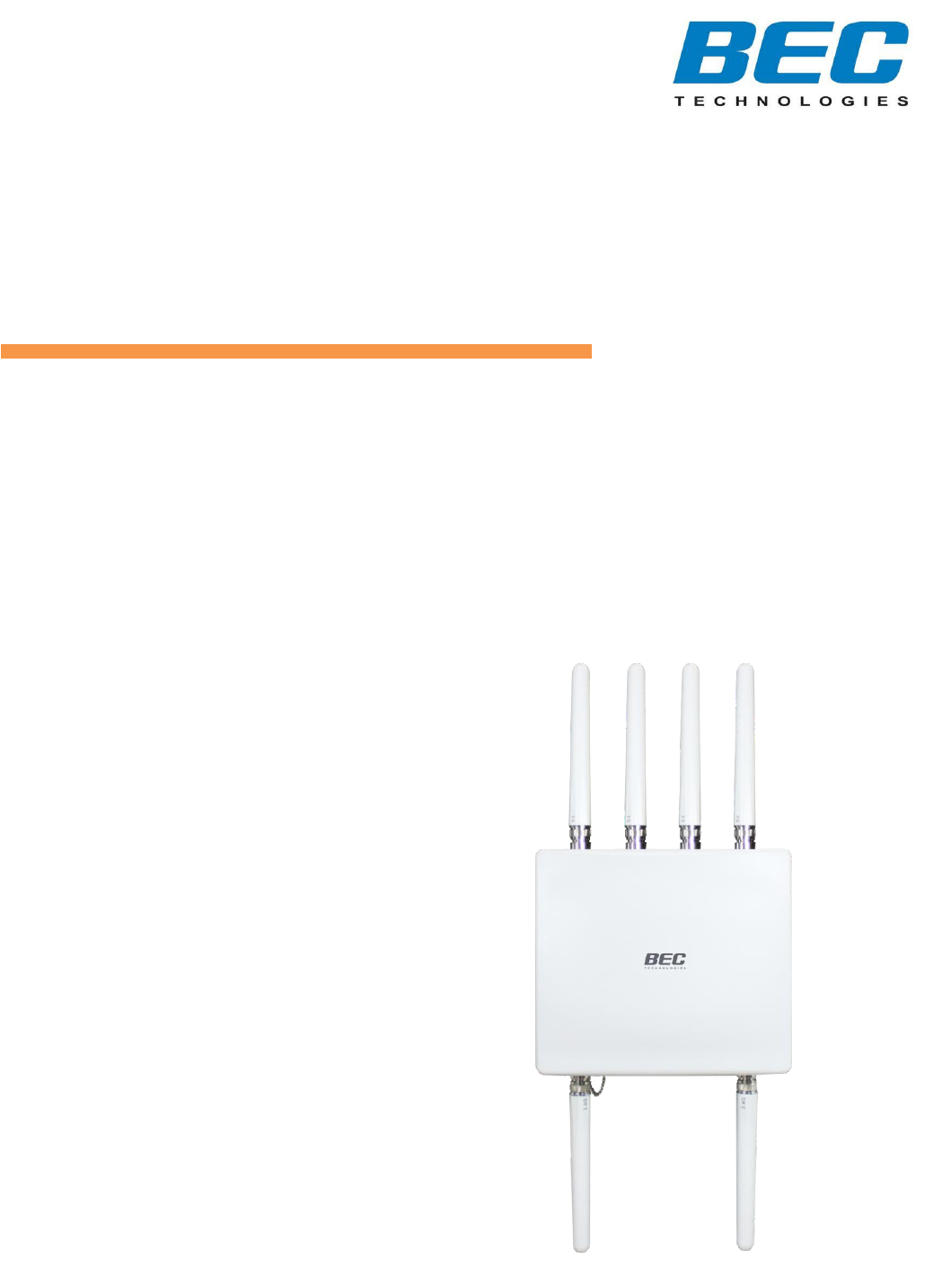
Introduction 1 CHAPTER 1: INTRODUCTION Introduction to your Router Congratulations on your purchase of the BEC 4700A / AZ ((4G/LTE) Wireless Outdoor Router). This unit is a lightweight, an industrial-grade outdoor fixed wireless router with an IP68 rated enclosure to withstand extreme weather conditions and harsh rugged deployments. With integrated IEEE802.3at power over Ethernet (PoE) support, the BEC 4700A/AZ provides an easy installation from eliminating the need for a separate power and data cable.
Introduction 2 wider coverage, the built-in Wireless Distribution System (WDS) repeater function expands the wireless network without needing any external wires or cables. IPv6 Supported Internet Protocol version 6 (IPv6) is a version of the Internet Protocol that is designed to succeed IPv4. IPv6 has a vastly larger address space than IPv4. The router is already supporting IPv6, you can use it in IPv6 environment no need to change device.
Introduction Features & Specifications 3 Features & Specifications • High-speed 4G connection up to downlink 100/300Mbps and uplink 50Mbps data rate (4700AZ) • Outdoor 4G for high speed mobile connectivity (4700AZ) • 4G embedded with a built-in SIM card slot (4700AZ) • 4G Management Center for connection monitoring (4700AZ) • Concurrent 2.
Introduction Features & Specifications 4 Firewall • Built-in NAT Firewall • Stateful Packet Inspection (SPI) • DoS attack prevention including Land Attack, Ping of Death, etc. • Access control • IP&MAC filter, URL Content Filter • Password protection for system management • VPN pass-through Quality of Service Control •Traffic prioritization management based-on Protocol, Port Number, and IP Address (IPv4/ IPv6) Carrier Grade Wireless LAN • Compliant with IEEE 802.11 a/b/g/n/ac standards • 2.
Introduction Features & Specifications • Web-based GUI for remote and local management (IPv4/IPv6) • Firmware upgrades and configuration data upload and download via web-based GUI • Supports DHCP server / client / relay • Supports SNMP v1, v2, v3, MIB-I and MIB-II • TR-069 supports remote management BEC 4700A / 4700AZ User Manual 5
Introduction Hardware Specifications 6 Hardware Specifications Physical interface • (2) 10/100/1000 Gigabit Ethernet LAN with IEEE802.3at compliant Gigabit PoE PD • IEEE 802.3at PD complaint (25.5W) • (6) Wireless N-Type Connectors with arrester • SIM slot (for the SIM from Telco / ISP) (4700AZ) • Reset Button • LED Indicators: (4700AZ) Power/Boot, LAN(PoE), EWAN, WI-FI(2.
Introduction Application Diagram Application Diagram 4700AZ BEC 4700A / 4700AZ User Manual 7
Product Overview CHAPTER 2: PRODUCT OVERVIEW Important Note for Using This Router ✓ ✓ Attention ✓ Do not remove, open or repair the case yourself. Contact with your Internet Service Provider or have it repaired at a qualified service center. Use the supplied PoE (Power-over-Ethernet) injector for indoor only or with any 802.3at capable PoE injectors to connect with the BEC 4700A/AZ. It is mandatory to earth ground the BEC 4700A/AZ.
Product Overview Device Description (Hardware Overview (BEC 4700A)) 9 Device Description Hardware Overiew (BEC 4700AZ) 2 3 1 11 PORT & LED 456 7 11 8 4 9 4 10 11 1 11 MEANING 1 WIFI Antenna Connectors (2.4GHz) Screw the supplied 2.4GHz antennas onto the antenna connectors on both sides. 2 RESET After the device is powered on, press it 6 seconds or above: to restore to factory default settings (this is used when you cannot login to the router, e.g.
Product Overview Device Description (Hardware Overview (BEC 4700A)) PORT & LED LTE LED 6 7 8 (Received Signal Strength Indicator) 10 MEANING Green RSSI greater than -69 dBm. Excellent signal condition Green Flashing Quickly RSSI from -81 to -69 dBm. Good signal condition Orange Flashing Quickly RSSI from -99 to -81 dBm. Fair signal condition Orange Flashing Slowly RSSI less than -99 dBm.
Product Overview Device Description (Hardware Overview (BEC 4700A)) 11 Hardware Overiew (BEC 4700A) 2 3 45 6 4 1 9 PORT & LED 9 7 4 8 9 1 9 MEANING 1 WIFI Antenna Connectors (2.4GHz) Screw the supplied 2.4GHz antennas onto the antenna connectors on both sides. 2 RESET After the device is powered on, press it 6 seconds or above: to restore to factory default settings (this is used when you cannot login to the router, e.g. forgot your password) 3 2.
Product Overview Device Description (Hardware Overview (BEC 4700A)) PORT & LED 5 6 12 MEANING Green System is up and ready Red Boot failure Green IP connected; WAN connection is ready Red IP request failed Off Either in bridged mode or WAN connection is not available Power LED Internet LED Use an outdoor Ethernet cable to connect to any Ethernet equipment.
Product Overview Mounting Kit Installation Mounting Kit Installation Mounting Kit includes: ❖ Articulation Pole x 1 ❖ T-formed Bracket x 1 ❖ Stainless Hose Clamp x 2 M8 Nut x 1 Articulation Pole x 1 ❖ M8x40 Screw Bolt x 1 M8 Washer x 1 ❖ M8 Nut x 1 M6 Washer x 4 ❖ M8 Washer x 1 ❖ M6 Washer x 4 T-form Bracket x 1 Spring Washer M8 x 1 Spring Washer M6 x 4 ❖ Spring Washer M8 x 1 ❖ Spring Washer M6 x 4 ❖ M6x16 Screw x 4 M6 x 16 Screw x 4 M8x40 Screw Bolt x 1 For Wall Mount Installation, you will nee
Product Overview Mounting Kit Installation 1. Attach the Articulation Pole to the Enclosure Attach the articulation pole to the back of the BEC 4700A/AZ enclosure using the supplied M6 screws, M6 spring washers and M6x16 screws which are included in the mounting kit. 1 2 M6x16 Screw M6 Spring Washer M6 Washer 3 Tool Advice: Use #10 HEX. Wrench to tighten or loosen the bolt(s).
Product Overview Mounting Kit Installation 15 Note: The flexible mounting kit can be adjusted in multiple angles to align with the base station for higher efficiency.
Product Overview Mounting Kit Installation 16 2. Wall or Pole Mount Installation 2.1 Mounting on Wall Fix the T-formed Bracket to the wall by using wood screws and Gyprock plugs. 2.2 Mounting on a Pole between 1.5” to 2” (38.1 ~ 50.8mm) Attach the T-formed Bracket and the W-bar to the pole then use M6x60 bolts, M6 spring washers and M6 washers to fix the mounting kit onto the pole. 2.3 Mounting on a Pole between 1” to 3” (25.4 ~ 76.
Product Overview Mounting Kit Installation Use the stainless hose clamps through the T-formed Bracket. Fix the T-formed Bracket to the pole by using the supplied stainless hose clamps. Use a flat-head screwdriver to turn the head of the screw clockwise to tighten it. 3. Install the Articulation Pole with the T-formed Bracket Attach the articulation pole (BEC 4700A/AZ enclosure) to the T-formed bracket using the supplied M8 nut, M8 spring washer, M8 washer and M8x40 screw bolt.
Product Overview Mounting Kit Installation 18 Attach the grounding wire to the BEC 4700A/AZ and tighten the screw 5.
Product Overview Router Installation Instructions 19 Router Installation Instructions 1. Power on your BEC 4700A/AZ Step 1: Assemble M25 cable gland Step 2: Unscrew the WAN/PoE IN port and insert the supplied outdoor Ethernet cable (RJ-45) through material A-D, and then connect the RJ-45 Ethernet cable into the WAN/PoE IN port. Step 3: 3.1: Insert ○ C at the back end of ○ D 3.2: clip ○ B on ○ C 3.3: keep ○ B close to ○ D 3.
Product Overview Router Installation Instructions 20 Step 4: Powering via PoE Injector: Insert the other end of outdoor Ethernet cable (RJ-45) to the supplied Gigabit PoE injector Data+Power port. Connect another Ethernet cable (RJ-45) directly to the Data port and the other end of cable to a switch or broadband router. Powering via a PoE Switch: Connect the Ethernet cable (RJ-45) from the 4700A/AZ directly to a PoE port on the switch.
Product Overview Router Installation Instructions 21 Step 1 (4700AZ Only): Unscrew the cap of SIM card slot. Step 2 (4700AZ Only): Slide the SIM card with the mental contacts (gold plate) facing down to the SIM slot then push it all the way in until you hear the clicking sound. It is recommended to use an industrial-grade SIM card.
Product Overview Router Installation Instructions Step 3 (4700AZ Only): Screw the cap back tightly. Please power off the device before inserting or removing the SIM card.
Product Overview System Recovery Procedure 23 System Recovery Procedures The purpose is to allow users to restore the BEC 4700A/AZ to its initial stage when the device is outage, upgraded to a wrong / broken firmware, cannot access to the GUI with wrong username and/or password, etc. Step 1 – Configure your PC Network IP Address Before performing the system recovery, assign this IP address and Netmask to your PC, 192.168.1.100 and 255.255.255.0 respectively. Step 2 – Reset your BEC 4700A/AZ Device 2.
Basic Installation 24 CHAPTER 3: BASIC INSTALLATION The router can be configured with your web browser. A web browser is included as a standard application in the following operating systems: Windows 7 / 8 / 10, Linux, Mac OS, etc. The product provides an easy and user-friendly interface for configuration.
Basic Installation Network Configuration – Windows 10 (IPv4) Network Configuration – IPv4 Configuring PC in Windows 10 (IPv4) 1. Click . 2. Click 3. Then click on Network and Internet. 4. Under Related settings, Network and Sharing Center 5. When the Network and Sharing Center window pops up, select and click on Change adapter settings on the left window panel. 6. Select the Local Area Connection, and right click the icon to select Properties.
Basic Installation Network Configuration – Windows 10 (IPv4) 7. Select Internet Protocol Version 4 (TCP/IPv4) then click Properties. 8. In the TCP/IPv4 properties window, select the Obtain an IP address automatically and Obtain DNS Server address automatically radio buttons. Then click OK to exit the setting. 9. Click OK again in the Local Area Connection Properties window to apply the new configuration.
Basic Installation Network Configuration – Windows 7/8 (IPv4) Configuring PC in Windows 7/8 (IPv4) 1. Go to Start. Click on Control Panel. 2. Then click on Network and Internet. 3. When the Network and Sharing Center window pops up, select and click on Change adapter settings on the left window panel. 4. Select the Local Area Connection, and right click the icon to select Properties.
Basic Installation Network Configuration – Windows 7/8 (IPv4) 5. Select Internet Protocol Version 4 (TCP/IPv4) then click Properties. 6. In the TCP/IPv4 properties window, select the Obtain an IP address automatically and Obtain DNS Server address automatically radio buttons. Then click OK to exit the setting. 7. Click OK again in the Local Area Connection Properties window to apply the new configuration.
Basic Installation Network Configuration – Windows Vista (IPv4) Configuring PC in Windows Vista (IPv4) 1. Go to Start. Click on Network. 2. Then click on Network and Sharing Center at the top bar. 3. When the Network and Sharing Center window pops up, select and click on Manage network connections on the left window panel. 4. Select the Local Area Connection, and right click the icon to select Properties.
Basic Installation Network Configuration – Windows Vista (IPv4) 5. Select Internet Protocol Version 4 (TCP/IPv4) then click Properties. 6. In the TCP/IPv4 properties window, select the Obtain an IP address automatically and Obtain DNS Server address automatically radio buttons. Then click OK to exit the setting. 7. Click OK again in the Local Area Connection Properties window to apply the new configuration.
Basic Installation Network Configuration – Windows 10 (IPv6) Network Configuration – IPv6 Configuring PC in Windows 10 (IPv6) 1. Click . 2. Click 3. Then click on Network and Internet. 4. Under Related settings, Network and Sharing Center 5. When the Network and Sharing Center window pops up, select and click on Change adapter settings on the left window panel. 6. Select the Local Area Connection, and right click the icon to select Properties.
Basic Installation Network Configuration – Windows 10 (IPv6) 7. Select Internet Protocol Version 6 (TCP/IPv6) then click Properties. 8. In the TCP/IPv6 properties window, select the Obtain an IPv6 address automatically and Obtain DNS Server address automatically radio buttons. Then click OK to exit the setting. 9. Click OK again in the Local Area Connection Properties window to apply the new configuration.
Basic Installation Network Configuration – Windows 7/8 (IPv6) Configuring PC in Windows 7/8 (IPv6) 1. Go to Start. Click on Control Panel. 2. Then click on Network and Internet. 3. When the Network and Sharing Center window pops up, select and click on Change adapter settings on the left window panel. 4. Select the Local Area Connection, and right click the icon to select Properties.
Basic Installation Network Configuration – Windows 7/8 (IPv6) 5. Select Internet Protocol Version 6 (TCP/IPv6) then click Properties. 6. In the TCP/IPv6 properties window, select the Obtain an IPv6 address automatically and Obtain DNS Server address automatically radio buttons. Then click OK to exit the setting. 7. Click OK again in the Local Area Connection Properties window to apply the new configuration.
Basic Installation Network Configuration – Windows Vista (IPv6) Configuring PC in Windows Vista (IPv6) 1. Go to Start. Click on Network. 2. Then click on Network and Sharing Center at the top bar. 3. When the Network and Sharing Center window pops up, select and click on Manage network connections on the left window panel. 4. Select the Local Area Connection, and right click the icon to select Properties.
Basic Installation Network Configuration – Windows Vista (IPv6) 5. Select Internet Protocol Version 6 (TCP/IPv6) then click Properties. 6. In the TCP/IPv6 properties window, select the Obtain an IP address automatically and Obtain DNS Server address automatically radio buttons. Then click OK to exit the setting. 7. Click OK again in the Local Area Connection Properties window to apply the new configuration.
Basic Installation Default Settings 37 Default Settings Before configuring the router, you need to know the following default settings. Web Interface: (Username and Password) Administrator Username: admin Password: admin If you ever forget the username/password to login to the router, you may press the RESET button up to 6 seconds then release it to restore the factory default settings.
Basic Installation Default Settings 38 Information from Your ISP Before configuring this device, you have to check with your ISP (Internet Service Provider) what kind of service is provided, Dynamic IP address, Static IP address, PPPoE or Bridge Mode). Gather the information as illustrated in the following table and keep it for reference. Username, Password, Service Name, and Domain Name PPPoE System (DNS) IP address (it can be automatically assigned by your ISP when you connect or be set manually).
Device Configuration Login to Your Device 39 CHAPTER 4: DEVICE CONFIGURATION Login to your Device Open your web browser, enter the IP address of your router, which by default is 192.168.1.254, and click “Go”, a username and password window prompt appears. The default username & password is “admin” & “admin” respectively for the Administrator. NOTE: This username / password may vary by different Internet Service Providers.
Device Configuration Login to Your Device 40 Once you have logged on to your BEC 4700A/AZ via your web browser, you can begin to set it up according to your requirements. On the configuration homepage, the left navigation pane links you directly to the setup pages, which includes: Section Status Device Info System Status System Log 4G-LTE Status (4700AZ) Configuration Interface Setup - Internet LAN Wireless 2.4G / 5G Wireless 2.
Device Configuration Login to Your Device - 41 Firmware & Configuration System Restart Auto Reboot Diagnostic Tool Please see the relevant sections of this manual for detailed instructions on how to configure your BEC 4700A/AZ.
Device Configuration Status – Device Info 42 Status Device Info It provides brief status summary of the device. Device Information Model Name: Name of the router for identification purpose. Firmware Version: Software version currently loaded in the router. MAC Address: A unique number that identifies the router. Data Time: Setup correct time on the BEC 4700A/AZ with your PC. Check on Time Zone section for more configuration information.
Device Configuration Status – Device Info 43 IP Address: WAN port IP address. Default Gateway: The IP address of the default gateway. LAN IP Address: LAN port IPv4 address. Subnet Mask/Prefix Length: Display LAN port IP subnet mask of IPv4 and/or Prefix length of IPv6. DHCP Server: Display LAN DHCP status of IPv4 and IPv6. Enable / 192.168.1.100~199: DHCPv4 server status on or off / DHCP IP range. Enable / Stateless: DHCPv6 server status on or off / DHCPv6 server Type.
Device Configuration Status – System Status & System Log 44 System Status System status displays the current router system (CPU and Memory) usage. CPU Usage: Display the amount of CPU’s processing capacity is being used in percentage (%). Higher the % rate may result in slow Internet loading, experiencing video lags, etc. To reduce high CPU consumption by resetting the device, power off and on, the easiest way to regain the service.
Device Configuration Status – 4G-LTE Status 45 4G/LTE Status This page contains 4G/LTE connection information. Status: Display current status of the 4G/LTE connection. SIM Status: Identify current status of the SIM, Activate or SIM Card Not Found. Signal Strength: The signal strength bar and dBm value indicates the current 4G/LTE signal strength. The front panel 4G/LTE Signal Strength LED indicates the signal strength as well. Network Name: The name of the LTE network the router is connecting to.
Device Configuration Status – 4G-LTE Status Amount Used: Display the amount of mobile data used and remaining in current billing cycle. Billing Cycle: Display the start date and number of days remaining in current billing cycle. Clean: Reset current saved mobile usage. Save: Click to save current mobile status to ROM.
Device Configuration Status – Wireless Status 47 Wireless Status MAC: The MAC of the connected wireless device. SSID: Display the total bytes transmitted till the latest second for the current connection for the current connection. RSSI: Display the signal strength between the wireless client and the AP (Access Point). RX / TX Rate: Display the current data reception (RX) and transmission (TX) rate, in Mbps, of the Wi-Fi client can use.
Device Configuration Status – Hotspot Status 48 Hotspot Status The status table displays a list of connected Wi-Fi clients via the hotspot. . Action: Click Drop to terminate the Wi-Fi connection of the client to the wireless network. MAC Address: The MAC of the connected wireless device. IP Address: The LAN IP address assigned to the wireless device. Authentication: Identification of the wireless device is being authorized or not. Username: The authentication username used to login to the hotspot.
Device Configuration Status – Statistics (4G/LTE) 49 Statistics ❖ 4G-LTE Status Take 4G/LTE as an example to describe the following connection transmission information. Traffic Statistics Interface: List all available network interfaces in the router. You are currently checking on the physical status of CBRS interface. Transmit Statistics Transmit Frames of Current Connection: Display the total number of 4G/LTE frames transmitted until the latest second for the current connection.
Device Configuration Status – Statistics (Ethernet WAN) ❖ 50 Ethernet WAN Traffic Statistics Interface: List all available network interfaces in the router. You are currently checking on the physical status of the WAN port. Transmit Statistics Transmit Frames: Display the number of frames transmitted until the latest second. Transmit Multicast Frames: Display the number of multicast frames transmitted until the latest second.
Device Configuration Status – Statistics (Ethernet LAN) 51 ❖ Ethernet Traffic Statistics Interface: List all available network interfaces in the router. You are currently checking on the physical status of the Ethernet port. Transmit Statistics Transmit Frames: Display the number of frames transmitted until the latest second. Transmit Multicast Frames: Display the number of multicast frames transmitted until the latest second.
Device Configuration Status –Statistics (Wireless 2.4G/5G) 52 ❖ Wireless 2.4G/5G Traffic Statistics Interface: List all available network interfaces in the router. You are currently checking on the physical status of the Wireless 5G. Transmit Statistics Transmit Frames: Display the number of frames transmitted until the latest second. Transmit Error Frames: Display the number of error frames transmitted until the latest second.
Device Configuration Status – DHCP Server & IPSec Status 53 DHCP Table DHCP table displays the devices connected to the router with clear information. Index #: The indication of the rule number. Host Name: Show the hostname of the PC. IP Address: The IP allocated to the device. MAC Address: The MAC of the connected device. Expire Time: The total remaining interval since the IP assignment to the PC. IPSec Status Index #: The numeric IPSec VPN tunnel/ rule. Action: Display Connect or Drop the connection.
Device Configuration Status – PPTP Status (PPTP Server & PPTP Client) 54 PPTP Status ❖ PPTP Server Index #: The numeric PPTP VPN tunnel/ rule. Connection Name: The profile name of the VPN connection/tunnel. Active: Display Yes or No to indicate the profile is enabled or disabled. Connection State: Display the VPN connection status. Connection Type: Display if VPN connection is for single PC use (Remote Access) or multi-user use (LAN to LAN).
Device Configuration Status – L2TP Status / GRE Status 55 L2TP Status Index #: The numeric L2TP VPN tunnel/rule indication. Connection Name: The profile name of the VPN connection/tunnel. Active: Display Yes or No to indicate the profile is enabled or disabled. Connection State: Display Yes/No to indicate the VPN connection status. Connection Mode: Display if L2TP mode is a dial-in or dial-out. Connection Type: Display if VPN connection is for single PC use (Remote Access) or multi-user use (LAN to LAN).
Device Configuration Status – OpenVPN Server / OpenVPN Client 56 OpenVPN Status ❖ OpenVPN Server Index #: The numeric OpenVPN tunnel/ rule. Connection Name: The profile name of the VPN connection/tunnel. Active: Display Yes or No to indicate the profile is enabled or disabled. Service Port: Display the port/protocol (1194/udp) used for OpenVPN connection. Tunnel Network: Display the virtual tunnel IP address and Netmask of the OpenVPN server.
Device Configuration Status – ARP Table / VRRP Status 57 ARP Table This section displays the router’s ARP (Address Resolution Protocol) Table, which shows the mapping of Internet (IP) addresses to Ethernet (MAC) addresses. This is useful as a quick way of determining the MAC address of the network interface of your PCs to use with the router’s Firewall - MAC Address Filter function. See the Firewall section of this manual for more information on this feature.
Device Configuration Quick Start 58 Quick Start This is a useful and easy utility to help you to setup the router quickly and to connect to your ISP (Internet Service Provider) with only a few steps. It will guide you step by step to setup password, time zone, wireless, and WAN settings of your device. The Quick Start Wizard is a helpful guide for the first-time users to the device. For detailed instructions on configuring WAN settings, see refer to the Interface Setup section.
Device Configuration Quick Start Step 4 – ISP Connection Type Set up your WAN Internet connection. 4.1 Select an appropriate WAN connection protocol then click NEXT to continue. 4.2 If selected 4G/LTE (for example) Input all relevant 4G/LTE parameters from your ISP. Click Next to save changes.
Device Configuration Quick Start 60 4.3 If selected EWAN / PPPoE, please enter PPPoE account information provided by your ISP. Click NEXT to continue. Step 5 – Quick Start Completed The Setup Wizard has completed. Click on BACK to make changes or correct mistakes. Click NEXT to save the current settings and complete the Quick Start setups. Go back to the Status > Device Info to view the status.
Device Configuration Interface Setup – Internet (4G/LTE) 61 Configuration Click to access and configure the available features in the following: Interface Setup, Dual WAN (4700AZ), Hotspot, Advanced Setup, VPN, Access Management, and Maintenance. These functions are described in the following sections. Interface Setup Here are the features under Interface Setup: Internet, LAN, Wireless 2.4G, Wireless MAC Filter, Wireless 5G, Wireless 5G MAC Filter, Wireless 5G Repeater, and Loopback.
Device Configuration Interface Setup – Internet (4G/LTE) 62 Status: Choose Activated to enable the 4G/LTE connection. Usage Allowance: Click Enable to activate the feature. Click the link to setup the usage settings. Period: Pick a period, Month or Day. Mode: Include Volume-based and Time-based control.
Device Configuration Interface Setup – Internet (4G/LTE) 63 the flow. Time-based control the flow by providing specific hours per month. ◼ 720 hours if selected period Month ◼ 12 hours if selected period Day The billing period begins on the beginning day of billing each month. Over usage allowance action: Here are actions to perform when mobile data usage, defined in Mode, reached to its maximum.
Device Configuration Interface Setup – Internet (4G/LTE) 64 ensure that an intruder has not replaced the client. Username/Password: Enter the username and password provided by your service provider. The username and password are case sensitive. PIN: PIN stands for Personal Identification Number. A PIN code is a numeric value used in certain systems as a password to gain access and authenticate. In mobile phones a PIN code locks the SIM card until you enter the correct code.
Device Configuration Interface Setup – Internet (WAN on Ethernet) ❖ 65 EWAN Bandwidth: Traffic/data control from WAN to LAN (Downstream) and LAN to WAN (Upload). Status: Select Activate / Deactivated to enable / disable the WAN service. IPv4/IPv6 IP Version: Choose IPv4, IPv4/IPv6, or IPv6 based on your environment. If you don’t know which one to choose from, please choose IPv4/IPv6 instead. ISP Connection Type ISP: Select the encapsulation type your ISP uses.
Device Configuration Interface Setup – Internet (WAN on Ethernet) 66 Default Route: Select Yes to use this interface as default route interface. TCP MTU Option: Enter the maximum packet that can be transmitted. Default MTU 0 means it is set to 1492 bytes. IPv4 Options NAT: Enable to allow BEC 4700A/AZ to assign private network IPs to all devices in the network for get Internet access. Client ID: It is known as DHCP Option 61. Enter the client identifier from your ISP.
Device Configuration Interface Setup – Internet (WAN on Ethernet) 67 - Obtain IPv6 DNS: Choose if you want to obtain DNS automatically. - Primary/Secondary: if you choose Disable in the Obtain IPv6 DNS field, please type the exactly primary and secondary DNS. - MLD Proxy: MLD (Multicast Listener Discovery Protocol) is to IPv6 just as IGMP to IPv4. It is a Multicast Management protocol for IPv6 multicast packets.
Device Configuration Interface Setup – Internet (WAN on Ethernet) 68 NAT: Enable to allow BEC 4700 to assign private network IPs to all devices in the network for get Internet access. Dynamic Route RIP Version: (Routing Information protocol) Select this option to specify the RIP version, including RIP-1, RIP-2. RIP Direction: Select this option to specify the RIP direction. - None is for disabling the RIP function.
Device Configuration Interface Setup – Internet (WAN on Ethernet) 69 Default Route: Select Yes to use this interface as default route interface. TCP MTU Option: Enter the maximum packet that can be transmitted. Default MTU 0 means it is set to 1492 bytes. IPv4 Options Get IP Address: Choose Static or Dynamic Static IP Address: If Static is selected in the above field, please enter the specific IP address you get from ISP and the following IP subnet mask and gateway address.
Device Configuration Interface Setup – Internet (WAN on Ethernet) 70 membership in a Multicast group. Choose whether enable IGMP proxy. IPv6 Options (only when choose IPv4/IPv6 or just IPv6 in IP version field above): IPv6 Address: Type the WAN IPv6 address from your ISP. Obtain IPv6 DNS: Choose if you want to obtain DNS automatically. Primary/Secondary: if you choose Disable in the Obtain IPv6 DNS field, please type the exactly primary and secondary DNS.
Device Configuration Interface Setup – LAN 71 LAN A Local Area Network (LAN) is a shared communication system to which many computers are attached and is limited to the immediate area, usually the same building or floor of a building. IPv4 Parameters IP Address: Enter the IP address of Router in dotted decimal notation, for example, 192.168.1.254 (factory default). IP Subnet Mask: The default is 255.255.255.0. User can change it to other such as 255.255.255.128.
Device Configuration Interface Setup – LAN 72 DHCP (Dynamic Host Configuration Protocol) allows individual clients to obtain TCP/IP configuration at start-up from a server. DHCPv4 Server: If set to Enabled, your BEC 4700A/AZ can assign IP addresses, default gateway and DNS servers to the DHCP client. If set to Disabled, the DHCP server will be disabled. If set to Relay, the BEC 4700A/AZ acts as a surrogate DHCP server and relays DHCP requests and responses between the remote server and the clients.
Device Configuration Interface Setup – LAN 73 IP Address: Enter the specific IP. For example: 192.168.1.110. MAC Address: Enter the responding MAC. For example: 00:0A:F7:45:6D:ED When added, you can see the ones listed as showed below: IPv6 Parameters The IPv6 address composes of two parts, thus, the prefix and the interface ID. Interface Address / Prefix Length: Enter a static LAN IPv6 address.
Device Configuration Interface Setup – LAN 74 information and parameters from a DHCPv6 server. The Server maintains a database that keeps track of which addresses have been assigned to which hosts. DHCPv6 Server: Click Enable to activate the DHCPv6 server. DHCPv6 Server Type: Select Stateless or Stateful. When DHCPv6 is enabled, this parameter is available.
Device Configuration Interface Setup – Wireless 2.4GHz 75 Wireless 2.4GHz This section introduces the wireless LAN and some basic configurations. Wireless LANs can be as complex as a number of computers with wireless LAN cards communicating through access points which bridge network traffic to the wired LAN. NOTE: WLAN (or BEC)1 / 2 / 3 / 4 Interface refers to as SSID1 / 2 / 3 / 4 Wi-Fi networks.
Device Configuration Interface Setup – Wireless 2.4GHz 76 802.11b and if you only have 802.11n then select 802.11n. Channel: The range of radio frequencies used by IEEE 802.11b/g/n wireless devices is called a channel. There are Regulation Domains and Channel ID in this field. The Channel ID will be different based on Regulation Domains. Select a channel from the drop-down list box. Beacon Interval: The Beacon Interval value indicates the frequency interval of the beacon.
Device Configuration Interface Setup – Wireless 2.4GHz 77 SSID Settings Available SSID: User can determine how many virtual SSIDs to be used. Default is 1, maximum is 4. SSID Index: Select the number of SSIDs you want to use; up to 4 SSIDs are available in the list. SSID: The SSID is the unique name of a wireless access point (AP) to be distinguished from another. For security propose, change the default SSID to a unique ID name to the AP which is already built-in to the router’s wireless interface.
Device Configuration Interface Setup – Wireless 2.4GHz 78 Security Type - WEP WEP Authentication Method: WEP authentication method, there are two methods of authentication used, Open System authentication (OPENWEB) and Share Key authentication (SHAREDWEB). We suggest you select OPENWEB. Key 1 to Key 4: Enter the key to encrypt wireless data. To allow encrypted data transmission, the WEP Encryption Key values on all wireless stations must be the same as the router.
Device Configuration Interface Setup – Wireless 2.4GHz 79 WDS Settings WDS (Wireless distributed system) is a wireless access point mode that enables wireless link and communication with other access point. It is easy to be installed, just define the peer’s MAC of the connected AP. WDS Mode: select Activated to enable WDS feature and Deactivated to disable this feature. MAC Address: Enter the AP MAC addresses (in XX:XX:XX:XX:XX:XX format) of the peer connected AP. Click Save to apply settings.
Device Configuration Interface Setup – Wireless 2.4G MAC Filter 80 Wireless MAC Filter The MAC filter screen allows you to configure the router to give exclusive access to up to 8 devices (Allow Association) or exclude up to 8 devices from accessing the router (Deny Association). Every Ethernet device has a unique MAC (Media Access Control) address. The MAC address is assigned at the factory and consists of six pairs of hexadecimal characters, for example, 00:AA:BB:00:00:02.
Device Configuration Interface Setup – Wireless 5GHz 81 Wireless 5GHz Access Point Settings Site Survey: Click to view all other available Wireless-AP devices near the BEC 4700A/AZ. CH (Channel): Channel ID used. SSID: The name of the wireless AP. BSSID: The MAC address of the wireless AP. Security: The security mode in the wireless AP. RSSI Signal (%): Signal strength of the wireless AP. Signal increases means the wireless AP is closer to your BEC 4700A/AZ and may cause interferences.
Device Configuration Interface Setup – Wireless 5GHz 82 a value between 1500 and 2347. Fragmentation Threshold: The threshold (number of bytes) for the fragmentation boundary for directed messages. It is the maximum data fragment size that can be sent. Enter a value between 256 and 2346, even number only. DTIM Interval: This value, between 1 and 255, indicates the interval of the Delivery Traffic Indication Message (DTIM). Channel Bandwidth: Select 20 MHz, 40 MHz or 80MHz for the channel bandwidth.
Device Configuration Interface Setup – Wireless 5GHz 83 Use WPS: Yes to enable the WPS. WPS State: Configured means Wi-Fi clients will use the default security setting of the SSID. WPS Mode: Pin Code means enrollee PIN code is required. WPS Progress: Click Start WPS to begin the WPS pairing process. Security Settings Security Type: You can disable or enable wireless security for protecting wireless network.
Device Configuration Interface Setup – Wireless 5GHz 84 WDS Mode: select Activated to enable WDS feature and Deactivated to disable this feature. MAC Address: Enter the AP MAC addresses (in XX:XX:XX:XX:XX:XX format) of the peer connected AP. Click Save to apply settings.
Device Configuration Interface Setup – Wireless (Example on WPS using PIN) 85 Example: WPS using PIN Method (Personal Information Number) PIN Method – Configure BEC 4700A/AZ as a Registrar 1. Jot down the client’s Pin (e.g. 04640776) from the WPS utility (e.g. Ralink Utility) 2. Enter the Enrollee (Client) PIN code and then press Start WPS. 3. Go back to the wireless client’s WPS utility (e.g. Ralink Utility). Set the Config Mode as Enrollee, press the WPS button on the top bar, select the AP (e.g.
Device Configuration Interface Setup – Wireless (Example on WPS using PIN) 86 4. The client’s SSID and security setting will now be configured to match the SSID and security setting of the registrar, the BEC 4700A/AZ router.
Device Configuration Interface Setup – Wireless (Example on WPS using PIN) 87 PIN Method – Configure BEC 4700A/AZ as an Enrollee 1. Jot down the AP PIN Code (e.g. 03454435) from the BEC 6300VNL. Press Start WPS. 2. Launch the wireless client’s WPS utility (e.g. Ralink Utility). Set the Config Mode as Registrar. Enter the PIN number in the PIN Code (e.g. 03454435) column then choose the correct AP (e.g. Billion_AP) from the WPS AP List before pressing the PIN button to run the scan.
Device Configuration Interface Setup – Wireless (Example on WPS using PIN) 88 3. The router’s (AP’s) SSID and security setting will now be configured to match the SSID and security setting of the registrar (client).
Device Configuration Interface Setup – Wireless 5G MAC Filter 89 Wireless 5G MAC Filter The MAC filter screen allows you to configure the router to give exclusive access to up to 8 devices (Allow Association) or exclude up to 8 devices from accessing the router (Deny Association). Every Ethernet device has a unique MAC (Media Access Control) address. The MAC address is assigned at the factory and consists of six pairs of hexadecimal characters, for example, 00:AA:BB:00:00:02.
Device Configuration Interface Setup – Wireless 5G Repeater 90 Wireless 5G Repeater Use the BEC 4700A/AZ as a repeater to extend the wi-fi signal of the primary AP. Manually Fill-in SSID: Enter the SSID of the primary AP. Security Type: Enter the Wi-Fi security type of the primary AP. WPA Algorithms: Enter the WPA algorithms of the primary AP. Pre-Shared Key: Enter the Wi-Fi password/pre-shared key of the primary AP.
Device Configuration Interface Setup – Loopback 91 Loopback Loopback interface is a widely known virtual interface, not the physical interface, on router and is highly robust and always up. The loopback interface has its own IP and subnet mask, often used for router management as Telnet management IP and involved in BGP as BGP Update-Source and OSPF as Router ID. IP Address: Enter a dedicated IP address for the loopback interface. IP Subnet Mask: Enter the subnet mask for the loopback interface.
Device Configuration Dual WAN – General Setting 92 Dual WAN Dual WAN, is a feature to have two independent Internet connection connected concurrently, offers a reliable Internet connectivity and maximize bandwidth utilization for critical applications delivery. General Setting Mode: Select a mode then click Save to proceed.
Device Configuration Dual WAN – General Setting (Failover & Failback) ❖ 93 Failover & Failback Auto failover/failback ensures always-online network connectivity. When primary WAN link (WAN1) fails, all traffic will switch over to the backup WAN (WAN2) seamlessly. Again, when the primary link is restored, traffic will be handled over from WAN2 to WAN1. WAN Port Service Detection Policy WAN1 (Primary): Choose a desired WAN as the primary WAN Link from the list.
Device Configuration Dual WAN – General Setting (Failover & Failback) 94 Failover/Fallback Rule Decisions: 1. Probe by Ping: Enable Ping to the gateway or an IP address Gateway: Internal system will wait for responses to the pings from the gateway of the WAN. Host: Internal system will wait for responses to the pings from a fixed IP address. Timeout X Seconds: Ping response time for each reply. Maximum timeout up to 5 seconds. 2.
Device Configuration Dual WAN – General Setting (Load Balance) ❖ 95 Load Balance Load balance aggregates the bandwidth of the two WAN links to optimize traffic distribution. NOTE: Go setup Outbound Load Balance mechanism after saving the settings. WAN Port Service Detection Policy WAN1 (Primary): Choose a desired WAN as the primary WAN Link from the list. WAN2 (Secondary): Choose a desired WAN as the backup WAN Link from the list. Service Detection: Enable to detect WAN connectivity automatically.
Device Configuration Dual WAN – Outbound Load Balance 96 Outbound Load Balance The connections are distributed over WAN1 and WAN2 so that it can utilize bandwidth of both WAN ports. With Outbound load balance, traffic may be routed to a faster link when one of the WAN links is slower or congested so that user gains better throughput and less delay. NOTE: Load Balancing must be enabled first. User can distribute outbound traffic based on Session Mechanism or IP Hash Mechanism.
Device Configuration Dual WAN – Protocol Binding 97 Protocol Binding Protocol Binding lets you direct specific traffic to go out from a specific WAN port. Policies determine how specific types of internet traffic are routed, for example, traffic from a specific IP address is granted access to only one WAN port rather than using both of the WAN ports as with load balancing. Rule Index: The numeric rule indicator. The maximum entry is up to 16.
Device Configuration Dual WAN – Protocol Binding BEC 4700A / 4700AZ User Manual 98
Device Configuration Hotspot – General Setting 99 Hotspot The Wi-Fi hotspot offers Internet access for mobile devices like smart phones, laptops, or smart pad to connect wirelessly in public locations such as in coffee shops, train station, airport, hotel, and much more. A captive portal with a login page will prompt on the mobile devices and require all Wi-Fi clients to accept the term of use before accessing to the Internet. General Setting Hotspot: Activate to enable the Wi-Fi hotspot feature.
Device Configuration 100 Hotspot – General Setting Authentication Authentication Methods: Two (2) network authentication methods, local built-in user account or a remote, external RADIUS server. If the credential matches, the Wi-Fi client is granted access to the network. RADIUS (an external authentication server) Primary RADIUS Server: The main IP address of the server. Secondary RADIUS Server: The backup IP address of the server, if any.