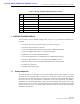
FCC ID: F8I-DLC0802A User Manual - Part 2 ADCP-75-150 • Preliminary Issue A • March 2003 • Section 2: Description Table 2-3. Remote Unit Outdoor Mounting Shelf User Interface REF NO DEVICE FUNCTIONAL DESCRIPTION 1 STM mounting slot Provides a mounting point for the STM module. 2 LPA mounting slot Provides a mounting point for the LPA module. 3 Grounding lug Provides a connection point for an external grounding cable. 4 AC power cable Provides AC power to the STM.
ADCP-75-150 • Preliminary Issue A • March 2003 • Section 2: Description 18634-A Figure 2-7. Spectrum Transport Module 5.2 Mounting The STM mounts within the RU outdoor cabinet or indoor mounting shelf. A runner on the bottom of the STM meshes with a track inside the cabinet/mounting shelf. The runner and track guide the STM into the installed position. The electrical interface between the STM and LPA is supported by a D-sub female connector located on the rear side of the STM.
ADCP-75-150 • Preliminary Issue A • March 2003 • Section 2: Description instead connects to a lightning protector that is mounted on the bottom of the cabinet (see Section 3.6). A coaxial jumper cable is provided (included with the enclosure) for connecting the STM connector to the lightning protector. 5.5 RF Signal Level Adjustment The STM is equipped with a digital attenuator for adjusting the signal level of the forward path RF output signal.
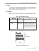
ADCP-75-150 • Preliminary Issue A • March 2003 • Section 2: Description (1) PORT 1 CONNECTOR (2) PORT 2 CONNECTOR (6) SERVICE CONNECTOR (3) ON/OFF SWITCH (7-13) LED INDICATORS (4) AC POWER CONNECTOR (14) ALARM CONNECTOR (5) DC POWER CONNECTOR (15) ANTENNA CONNECTOR 18636-A Figure 2-8. Spectrum Transport Module User Interface Table 2-4.
ADCP-75-150 • Preliminary Issue A • March 2003 • Section 2: Description Table 2-4. Spectrum Transport Module User Interface, continued REF NO USER INTERFACE DESIGNATION DEVICE FUNCTIONAL DESCRIPTION 8 STANDBY Multi-colored LED (green/yellow/red) Indicates if the system is in the Normal state (off) Standby state (blinking green), Test state (blinking red), or Program Load state (blinking yellow). See Note.
ADCP-75-150 • Preliminary Issue A • March 2003 • Section 2: Description STAT US MUTE NORM RESE T 18640-A Figure 2-9. Linear Power Amplifier 6.2 Mounting The LPA mounts within the RU outdoor cabinet or indoor mounting shelf. Runners on the top and bottom of the LPA mesh with tracks. The runners and tracks guide the LPA into the installed position. The electrical interface between the STM and LPA is supported by a D-sub female connector located on the rear side of the LPA.
ADCP-75-150 • Preliminary Issue A • March 2003 • Section 2: Description 6.5 Cooling Continuous air-flow for cooling is provided by a fan mounted at the front of the LPA housing. Cool air is pulled into the module from the front and heated air is exhausted out the back. An alarm is provided that indicates if a high temperature condition (>50º C/122º F) occurs or if a fan failure occurs. The fan may be field replaced if it fails. 6.
ADCP-75-150 • Preliminary Issue A • March 2003 • Section 2: Description 7 INTERFACE PANELS (ACCESSORY) The interface panels are accessory items that are used when multiple BTS’s and multiple HU’s require connection or when RF attenuation is needed between the BTS and HU. Two types of panels are available: the Conditioning Panel and the Duplexing Panel. The Conditioning Panel, shown in Figure 2-11, provides attenuation of the forward path signal to the level required for input to the HU.
ADCP-75-150 • Preliminary Issue A • March 2003 • Section 2: Description 8 WAVELENGTH DIVISION MULTIPLEXER (ACCESSORY) The Wavelength Division Multiplexer (WDM) module, shown in Figure 2-13, is an accessory item that is used in applications when it is desireable or necessary to combine the forward and reverse path optical signals from one Digivance system onto a single optical fiber.
ADCP-75-150 • Preliminary Issue A • March 2003 • Section 2: Description 9 COARSE WAVELENGTH DIVISION MULTIPLER SYSTEM (ACCESSORY) The Coarse Wavelength Division Multiplexer (CWDM) system is an accessory that is used when it is desireable or necessary to combine the forward and reverve path optical signals from up to four Digivance systems onto a single optical fiber. Each CWDM system consists of a CWDM Host module, CWDM Host module mounting shelf, and CWDM Remote module.
ADCP-75-150 • Preliminary Issue A • March 2003 • Section 2: Description 10 DIGIVANCE ELEMENT MANAGEMENT SYSTEM The Digivance Element Management System (DEMS) is a network management tool that provides control and monitoring functions for the Digivance system. The DEMS is used to provision and configure new systems for operation, set system operating parameters, get system alarm and status messages, and upgrade the system software.
ADCP-75-150 • Preliminary Issue A • March 2003 • Section 2: Description 10.2 Service Interface Connection The service interface connection between the DEMS computer and the HU or RU requires that the DEMS computer be equipped with a DB-9 connector that is configured to provide an RS232 DCE interface. A straight-through RS-232 interface cable (accessory item) equipped with a male DB-9 connector on one end and a PC-compatible connector on the other end is required to link the DEMS computer to the HU.